
Digital matrix control system and digital matrix control method for realizing multi-mode access

A technology of digital matrix and control system, applied in parts of TV system, parts of color TV, TV and other directions, can solve problems such as signal loss, and achieve the effect of enhancing transmission bandwidth

Inactive Publication Date: 2011-04-20
潘国平
View PDF5 Cites 11 Cited by
  • Summary
  • Abstract
  • Description
  • Claims
  • Application Information

AI Technical Summary

Problems solved by technology

[0004] The purpose of the present invention is to provide a digital matrix control system that realizes multi-mode access, so as to solve the technical problem of relatively serious signal loss in the transmission switching process in the prior art
[0005] The second purpose of the present invention is to provide a method for realizing multi-mode access to solve the technical problem of relatively serious signal loss in the transmission switching process in the prior art

Method used


Image

  • Digital matrix control system and digital matrix control method for realizing multi-mode access
  • Digital matrix control system and digital matrix control method for realizing multi-mode access
  • Digital matrix control system and digital matrix control method for realizing multi-mode access

Examples


Embodiment 1

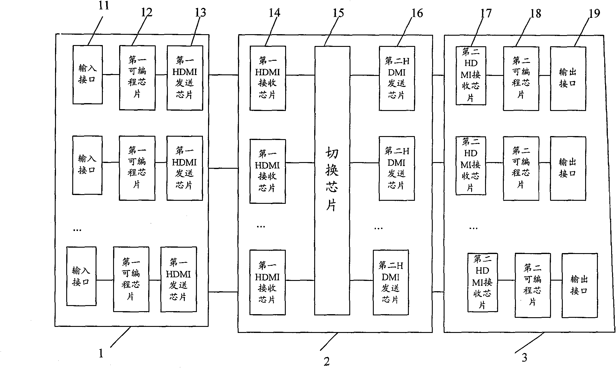
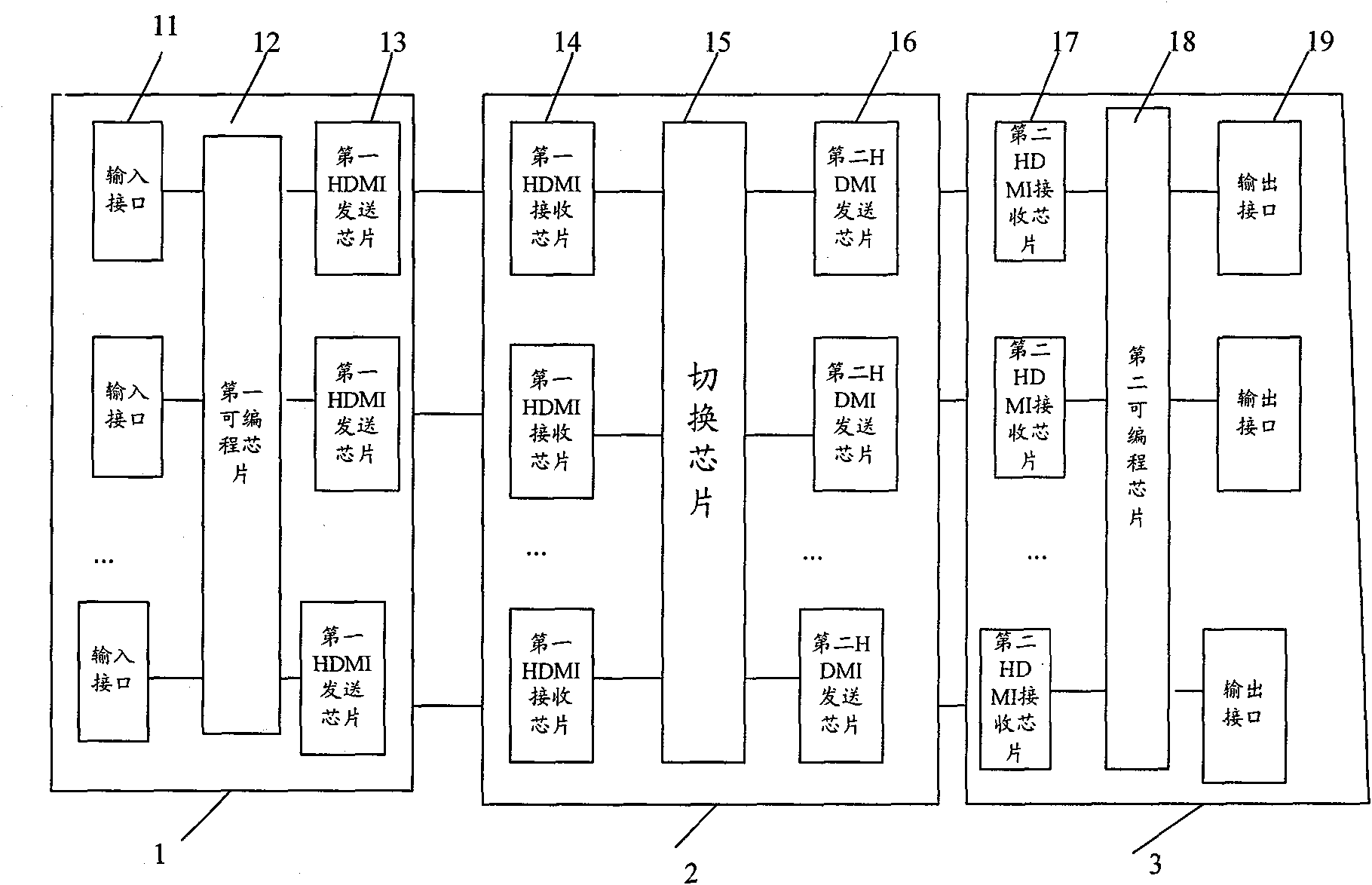
[0025] see figure 1 , which is a schematic diagram of a digital matrix control system for realizing multi-mode access in the present invention. Each matrix host includes a multi-channel input module 1, a digital crossover switch control module 2 and a multi-channel output module 3, wherein,

[0026] Each input module includes several input interfaces 11 , a first programmable chip 12 , and a first HDMI sending chip 13 . The input interface 11 is connected to the first programmable chip 12 , and the first programmable chip 12 is connected to the first HDMI sending chip 13 . The first programmable chip 12 is used to encode the received input data, for example, add a header before the input data, and the header data includes at least information indicating the attributes of the input interface 11 and the attributes of the input data. For example, the input interface 11 is the interface 5, and receives digital video data. Add the interface and attribute information on the messa...

Embodiment 2

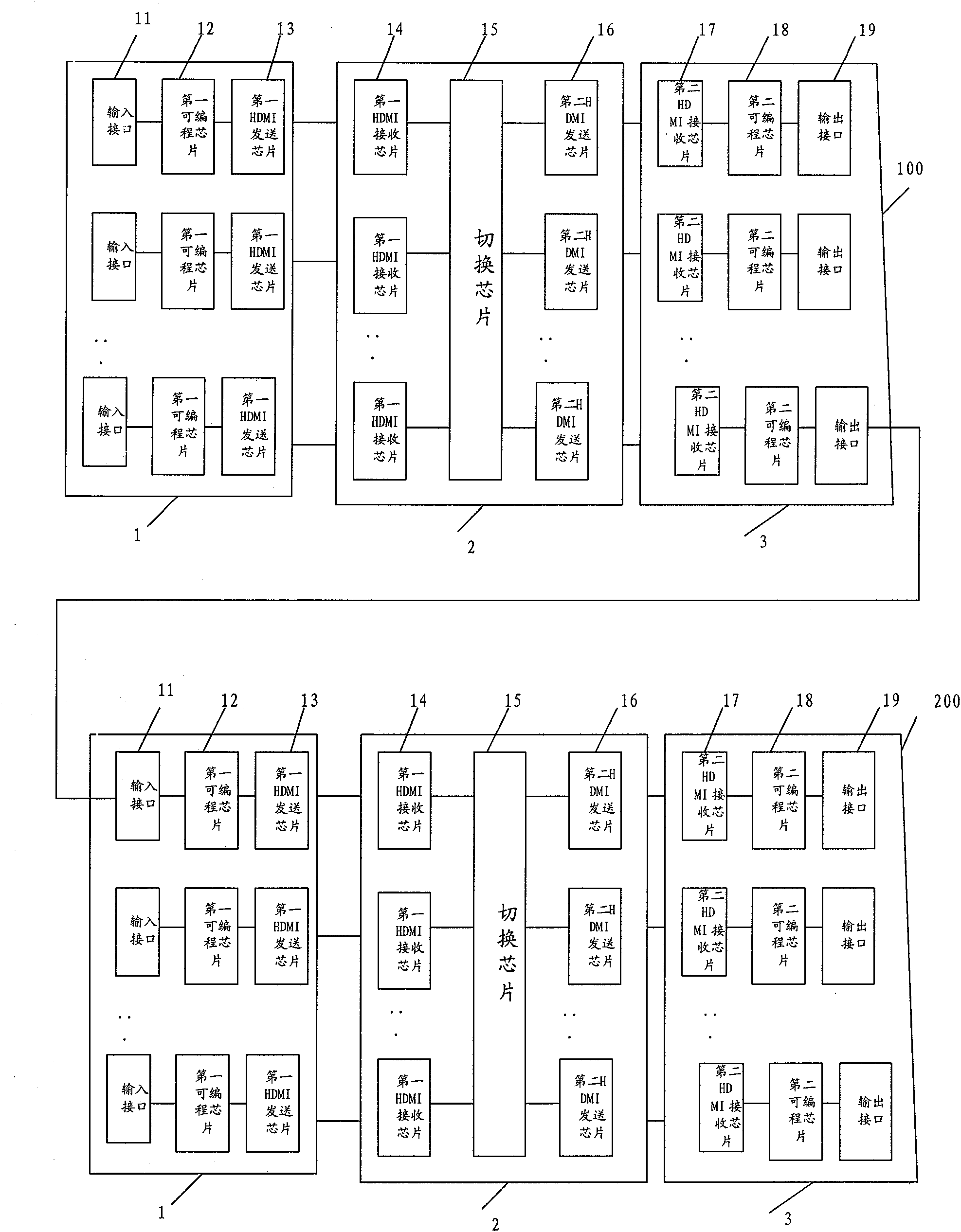
[0034] When multiple cabinets (matrix hosts) are cascaded, the transmission between cabinets adopts HDMI transmission and optical fiber transmission technology, and the signal loss is almost zero. In addition, the use of HDMI transmission has the advantages of anti-static, large transmission distance, and low price.

[0035]see image 3 , a multi-cascade digital matrix control system for multi-mode access, at least including a first matrix control subsystem 100 and a second matrix control subsystem 200, the first matrix control subsystem 100 includes a multi-channel input module, a digital crossover switching control module and multiple output module, wherein,

[0036] Each input module includes several input interfaces, a first programmable chip, and a first HDMI sending chip. The input interface is connected to a programmable receiving chip, and the programmable receiving chip is connected to an HDMI sending chip. The programmable receiving chip is used for Encoding the re...


PUM


Abstract

The invention relates to a digital matrix control system for realizing multi-mode access. An HDMI (High-Definition Multimedia Interface) transmission technology is adopted to complete the internal digital transmission of the system and data transmission among cascaded matrix hosts. Compared with the prior art, the invention has the following advantages that firstly, the HDMI technology is used skillfully to transmit any formats of data signals and greatly increase transmission bandwidth; next, when multiple machine cabinets (matrix hosts) are cascaded, the transmission among the machine cabinets adopts HDMI transmission technology and optical fiber transmission technology, and the signal loss is almost zero; in addition, the system has the advantages of static resistance, large transmission distance, low cost, and the like by using the HDMI transmission; and finally, digital signals are directly processed by the system and transmitted in the system, a transmission switching process causes no signal loss.

Description

technical field [0001] The invention relates to a digital matrix control system and method for realizing multi-mode access. Background technique [0002] With the increasing perfection of the digital monitoring system, especially the overall control of the switching matrix, it has really promoted the process of digitalization and networking of the matrix system. At present, in the security monitoring industry, traditional matrix systems and small-channel digital hard disk video recorders are mainly used. If a large and medium-sized monitoring system is established to realize the combination of analog and digital, multiple sets of matrices and other equipment are required to be used in combination, and There is no signal connection port between the traditional matrix system and the digital hard disk video recorder, and each digital hard disk video recorder must be connected to the matrix system through a video distributor, and information exchange between the systems cannot b...

Claims


Application Information

Patent Timeline
IPC IPC(8): H04N5/268H04N5/765
Inventor 潘国平
Owner 潘国平
Learn More