Vehicle-mounted system and bidirectional communication method
A vehicle-mounted system and vehicle-mounted equipment technology, applied in the direction of telephone communication, vehicle components, electrical components, etc., can solve the problems of RKE equipment, such as lack of human-machine interface and system processing capabilities, and cannot provide rich types, etc., to achieve a good human-computer interaction interface, The effect of extending the communication distance
- Summary
- Abstract
- Description
- Claims
- Application Information
AI Technical Summary
Problems solved by technology
Method used
Image
Examples
Embodiment 1
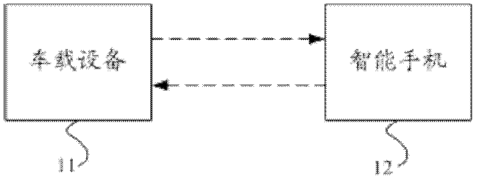
[0049] Embodiment 1 of the present invention provides a vehicle-mounted system, figure 1 It is a schematic structural diagram of the vehicle-mounted system. The vehicle-mounted system provided by the embodiment of the present invention includes a vehicle-mounted device 11 and a smart phone 12, wherein the smart phone 12 has a WiFi / Bluetooth interface, and the vehicle-mounted device has a WiFi / Bluetooth communication function. The vehicle-mounted system provided by the first embodiment of the present invention adopts the WiFi / Bluetooth communication method to realize the direct two-way communication between the vehicle-mounted device 11 and the smart phone 12 .
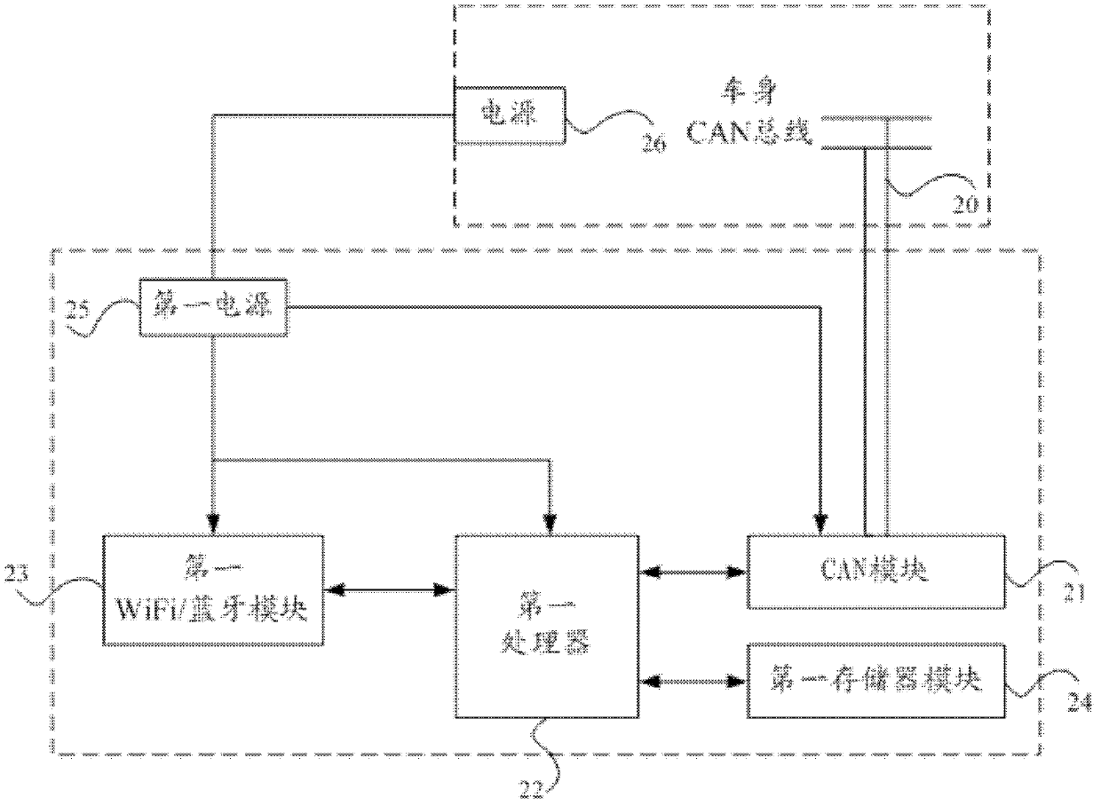
[0050] figure 2 for figure 1 A schematic structural diagram of the vehicle-mounted device 11 in the vehicle-mounted system, figure 2 The vehicle-mounted device 11 includes: a CAN module 21 , a first processor 22 , a first WiFi / Bluetooth module 23 , a first storage module 24 and a first power supply 25 . Wherein, t...
Embodiment 2
[0068] Embodiment 2 of the present invention provides a vehicle-mounted system, Figure 4 It is a schematic structural diagram of the vehicle-mounted system, including: vehicle-mounted equipment 41, portable card 42 and smart phone 43. The system uses RF communication technology to establish the connection between the vehicle-mounted equipment 41 and the portable card 42, and establishes the connection between the portable card 42 and the smart phone through WiFi / Bluetooth technology. The mobile phone 43 is connected, so as to realize the indirect two-way communication between the vehicle equipment 41 and the smart phone 43.
[0069] Figure 5 for Figure 4 A schematic structural diagram of the vehicle-mounted device 41 includes: a CAN module 51 , a first processor 52 , and a first RF module 53 . Wherein, the CAN module 51 is connected with the CAN bus 50 on the car, and is used to receive the data of the CAN bus 50, and resolve the data of the received CAN bus 50 into data ...
Embodiment 3
[0085] Embodiment 3 of the present invention provides a vehicle-mounted system, Figure 8 It is a schematic structural diagram of the vehicle-mounted system, including: vehicle-mounted equipment 81, a portable card 82 and a smart phone 83. The system can use Bluetooth / WiFi communication technology to realize direct two-way communication between the vehicle-mounted device 81 and the smart phone 83, and can also use The low-power RF communication technology realizes the indirect two-way communication between the on-vehicle device 81 and the smart phone 83 through the portable card 82, and can switch between the two communication modes.
[0086] Figure 9 for Figure 8 The structural diagram of the vehicle-mounted device 81 includes: a CAN module 91 , a first processor 92 , a first WiFi / Bluetooth module 93 , a first RF module 94 , a first storage module 95 and a first power supply 96 . Figure 10 for Figure 8 The structural diagram of the portable card 82 includes: a second R...
PUM
 Abstract
Description
Claims
Application Information
 - R&D
- Intellectual Property
- Life Sciences
- Materials
- Tech Scout
- Unparalleled Data Quality
- Higher Quality Content
- 60% Fewer Hallucinations
Browse by: Latest US Patents, China's latest patents, Technical Efficacy Thesaurus, Application Domain, Technology Topic, Popular Technical Reports.
© 2025 PatSnap. All rights reserved.Legal|Privacy policy|Modern Slavery Act Transparency Statement|Sitemap|About US| Contact US: help@patsnap.com


