Sliding assisting apparatus

a technology of sliding assist and sliding body, which is applied in the direction of door/window fittings, wing openers, constructions, etc., can solve the problems of poor convenience of use, difficult to assemble the movable body again on the main body, and lack of high quality, etc., to achieve excellent building-in characteristics and maintenance characteristics, improve convenience, and limited setup space

Inactive Publication Date: 2007-10-16
NIFCO INC
View PDF15 Cites 27 Cited by
  • Summary
  • Abstract
  • Description
  • Claims
  • Application Information

AI Technical Summary

Benefits of technology

[0014]In the present invention, at the case restrained position, one of the sliders is integrally linked to the case and does not slide independently (a locked position in which one of the sliders is integrally linked or operationally linked with the movable body). At the case restraint released position, one of the sliders is not linked to the case and is capable of sliding independently (an unlocked position in which the slider is unlinked with the movable body or released). Each lock member and each striker may be formed in a same shape, thereby shearing parts and reducing cost.
[0023]The apparatus has excellent simplicity as a construction in which the movable body is damped by the damper such that it is not rapidly slid by the force of the urging device, the damping force can be applied stably by means of the gear, and making the damping force act on only a part of the course of sliding of the sliders also becomes easier to realize.

Problems solved by technology

In a structure in which a movable body is switched to slide between a drawn-in position and a drawn-out position on a main body, as disclosed in Patent Document 1, it is tiresome and lacks a feeling of high quality as all of the switching operations are performed by a hand.
In the above-mentioned conventional structure, for example, although the movable body is slid automatically almost entirely from the drawn-out position to the drawn-in position, a strong pulling operation force by that amount becomes necessary when going from the drawn-in position to the drawn-out position, and the convenience of use becomes poor.
Moreover, in the conventional structure, once the movable body is removed from the main body, because it is drawn into the main body by the force of the spring member 65 in a state having the slot 61 turned upwardly as shown in FIG. 14(a) by releasing of the tilting part 60 from the drive pin 55, it is difficult to assemble the movable body again on the main body, and the drive pin 55, and the like, are easily damaged when the movable body is forcefully pushed in toward the side of the main body.
Also, in the conventional structure, the operational characteristics are limited in that it does not have functions for assisting both operations in the case of sliding the movable body in the direction of the drawn-in position and when sliding it in the direction of the drawn-out position.

Method used


Image

  • Sliding assisting apparatus
  • Sliding assisting apparatus
  • Sliding assisting apparatus

Examples


Embodiment Construction

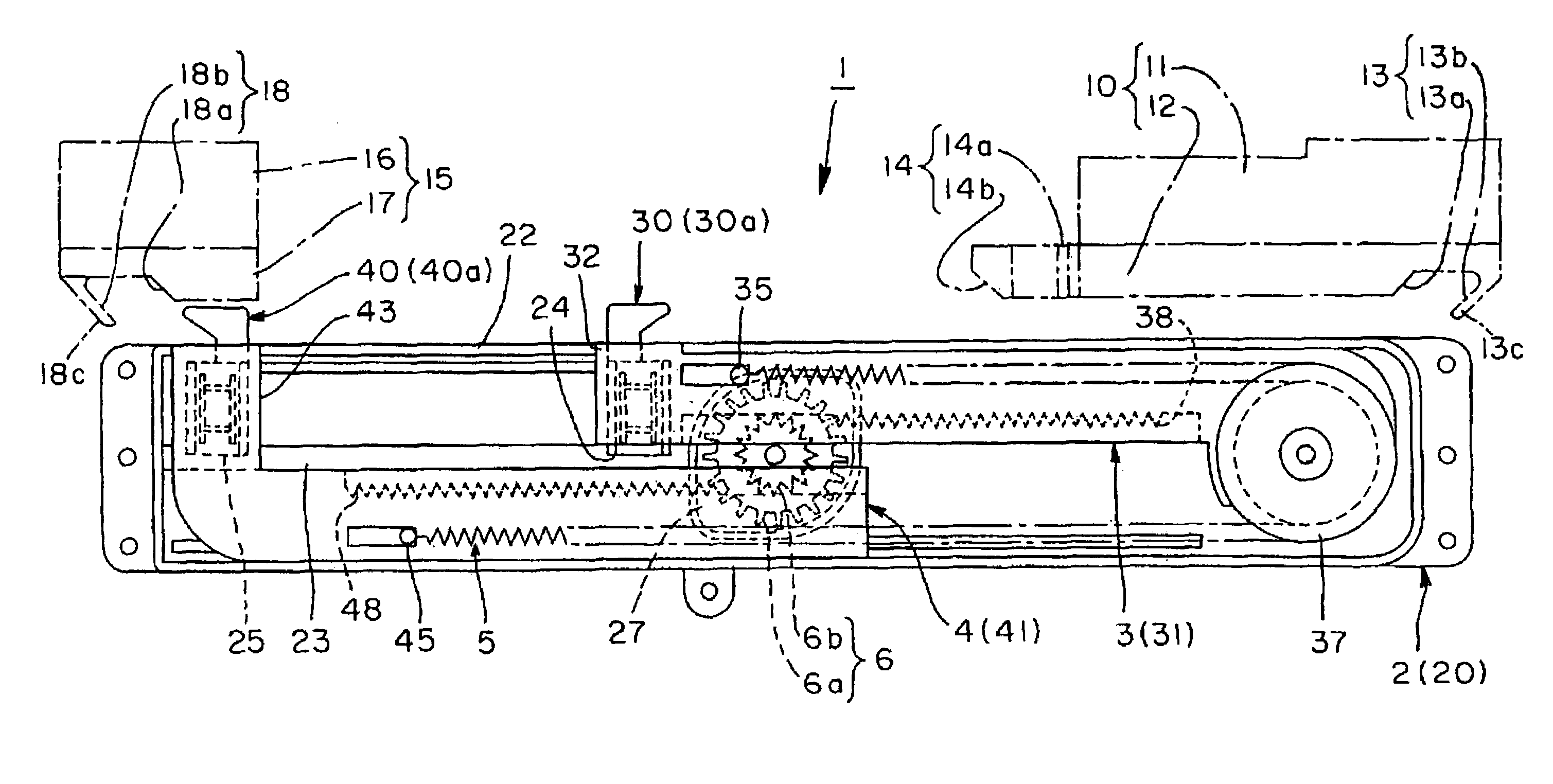
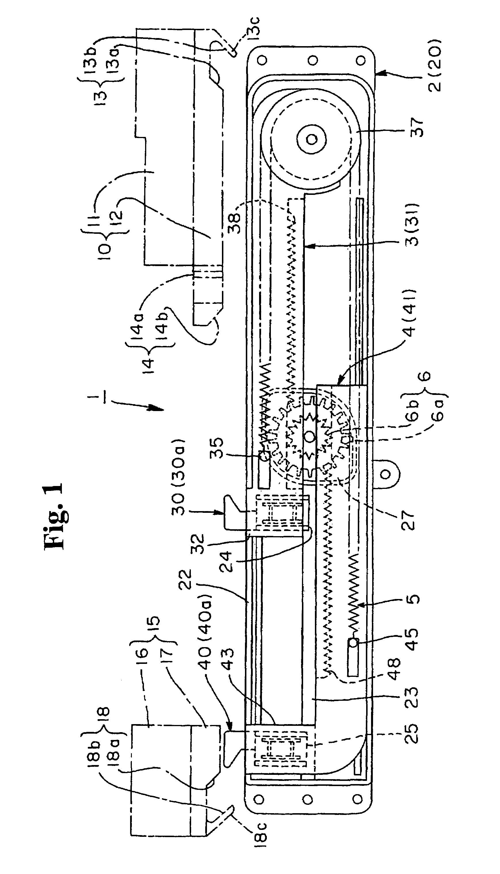
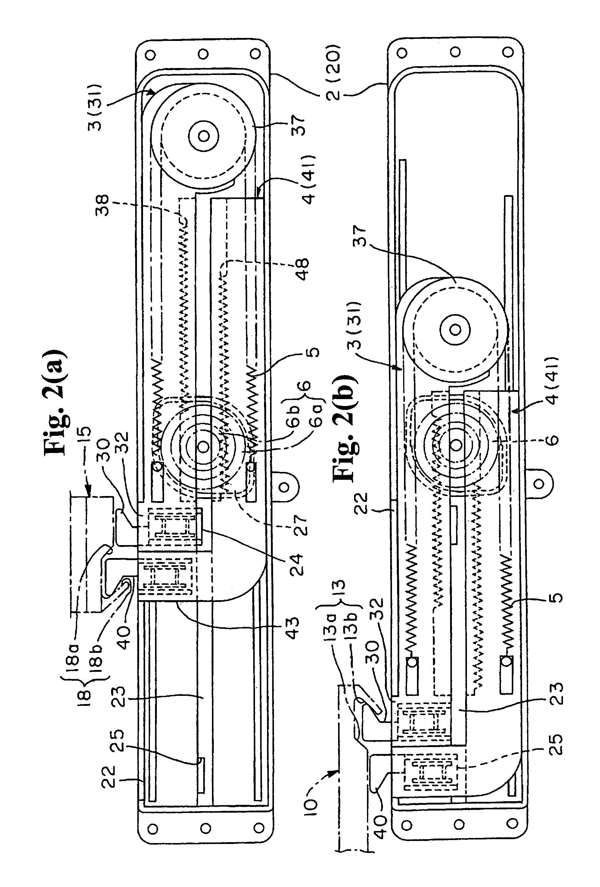
[0038]Hereunder, embodiments of the present invention will be explained with reference to the drawings. FIG. 1 and FIGS. 2(a) and 2(b) typically show the operation of the apparatus of the embodiment of the present invention. FIG. 1 is the state in which force is accumulated. FIGS. 2(a) and 2(b) are showing the state in which the force is released. FIG. 3 is structural drawings showing the relationships among the main components constituting said apparatus. FIGS. 4(a) and 4(b) are a top view and a side view showing the case main body of the apparatus together with the damper. FIG. 5 is a top view showing the cover attached to said case main body.

[0039]FIGS. 6(a) to 6(c) are one of the sliders constituting said apparatus; wherein FIG. 6(a) is a top view showing it together with the lock member, FIG. 6(b) is a side view, and FIG. 6(c) is a bottom view. FIGS. 7(a) to 7(c) are views showing the other slider; wherein FIG. 7(a) is a top view, FIG. 7(b) is a side view, and FIG. 7(c) is a bo...


PUM


Abstract

A sliding assisting apparatus assists a movable body to move between a drawn-out position and a drawn-in position. The apparatus includes a unit main body to be attached to a main body or the movable body, and a pair of strikers to be attached to the main body or movable body. The unit main body includes a pair of sliders slidably disposed inside a case, lock members movably supported on the respective sliders, coupling parts provided on the case for engaging the lock members, and an urging device provided between the sliders for accumulating a force when the sliders slide away from the other. One striker switches one slider between a case restrained position in which one coupling part engages one lock member and a case restraint released position in which the one coupling part releases the one lock member.

Description

BACKGROUND OF THE INVENTION AND RELATED ART STATEMENT[0001]The present invention relates to a sliding assisting apparatus for assisting an operation of a movable body such as a drawer or cover body to slide on a main body and switch between a drawn-in position and a drawn-out position.[0002]In a structure in which a movable body is switched to slide between a drawn-in position and a drawn-out position on a main body, as disclosed in Patent Document 1, it is tiresome and lacks a feeling of high quality as all of the switching operations are performed by a hand. Accordingly, it is dealt with in a manner such that the movable body is forced in either direction of the drawn-out position or the drawn-in position and is slid automatically toward the forced direction.[0003]FIGS. 14(a) and 14(b) show a drawer apparatus disclosed in Patent Document 1; wherein FIG. 14(a) is a state drawing of the drawn-in position of the movable body not illustrated, and FIG. 14(b) is the drawn-out position. ...

Claims


Application Information

Patent Timeline
Patent Type & Authority Patents(United States)
IPC IPC(8): A47B88/00A47B88/04E05F1/08E05F5/00
CPCA47B88/047A47B88/0477E05F1/16A47B88/0481E05F5/003E05Y2800/24E05Y2800/00E05Y2900/20A47B88/463A47B88/467A47B88/47A47B88/40E05F3/16E05F3/22E05F5/02E05F5/06
Inventor SATO, HIROJIKOBAYASHI, YASUTOMO
Owner NIFCO INC
Why Eureka
Try Eureka