Weatherproof receptacle cover with adapter plate

a technology for receptacle covers and adapters, which is applied in the direction of electrical apparatus, casings/cabinets/drawers, casings/cabinets/drawers details, etc., can solve the problems of time-consuming and inefficient installation, safety issues, and the inability of conventional covers to use with single-gang and/or double-gang electrical device configurations, etc., to achieve the effect of safe housing a plurality

Inactive Publication Date: 2007-10-16
HUBBELL INC
View PDF59 Cites 17 Cited by
  • Summary
  • Abstract
  • Description
  • Claims
  • Application Information

AI Technical Summary

Benefits of technology

[0007]Accordingly, what is needed is an electrical device cover that overcomes the drawbacks of conventional non-convertible covers, such as the inability of safely protecting electrical devices in varying orientations and in a variety of styles and sizes, through a cover that may interchangeably and safely accommodate virtually all commonly encountered electrical devices used in conjunction with electrical device boxes. Embodiments of the invention have the advantage of being able to solve these problems through a convertible electrical device cover that is adaptable to safely accommodate a plurality of electrical devices in a plurality of orientations.
[0015]In still another embodiment, the engaging mechanism may include electrical device box screws and opposing top and bottom key holes that extend fully through the adapter plate and that align with underlying opposing top and bottom key holes in the base plate. The electrical device box screws may extend through the key holes in both the adapter and base plates and into the electrical device box screws holes so that a rear side of the adapter plate may be removably coupled to a front side of the base plate and a front face of the electrical device may be held in at least a flush engagement with the front side of the adapter plate.

Problems solved by technology

However, conventional covers usually are non-convertible in their design, and therefore, each electrical device requires a different type of conventional cover configured for it.
Moreover, conventional covers usually are not capable of use with both single-gang and / or double-gang electrical device configurations.
Thus, to install or service electrical devices, an electrician must carry several types of conventional covers to each site, which are time consuming and inefficient to install.
Another problem currently facing conventional covers may involve safety issues.
Many conventional covers and related cover assemblies may be unsafe based on this fact.
Such a cover assembly may be unsafe if the thickness of the base is too great, the electrical device may not protrude far enough to be flush with or extend through the plastic or metal cover access openings respectively.

Method used


Image

  • Weatherproof receptacle cover with adapter plate
  • Weatherproof receptacle cover with adapter plate
  • Weatherproof receptacle cover with adapter plate

Examples


first embodiment

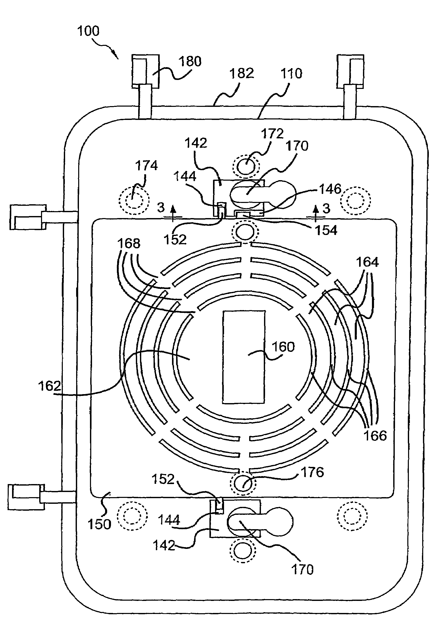
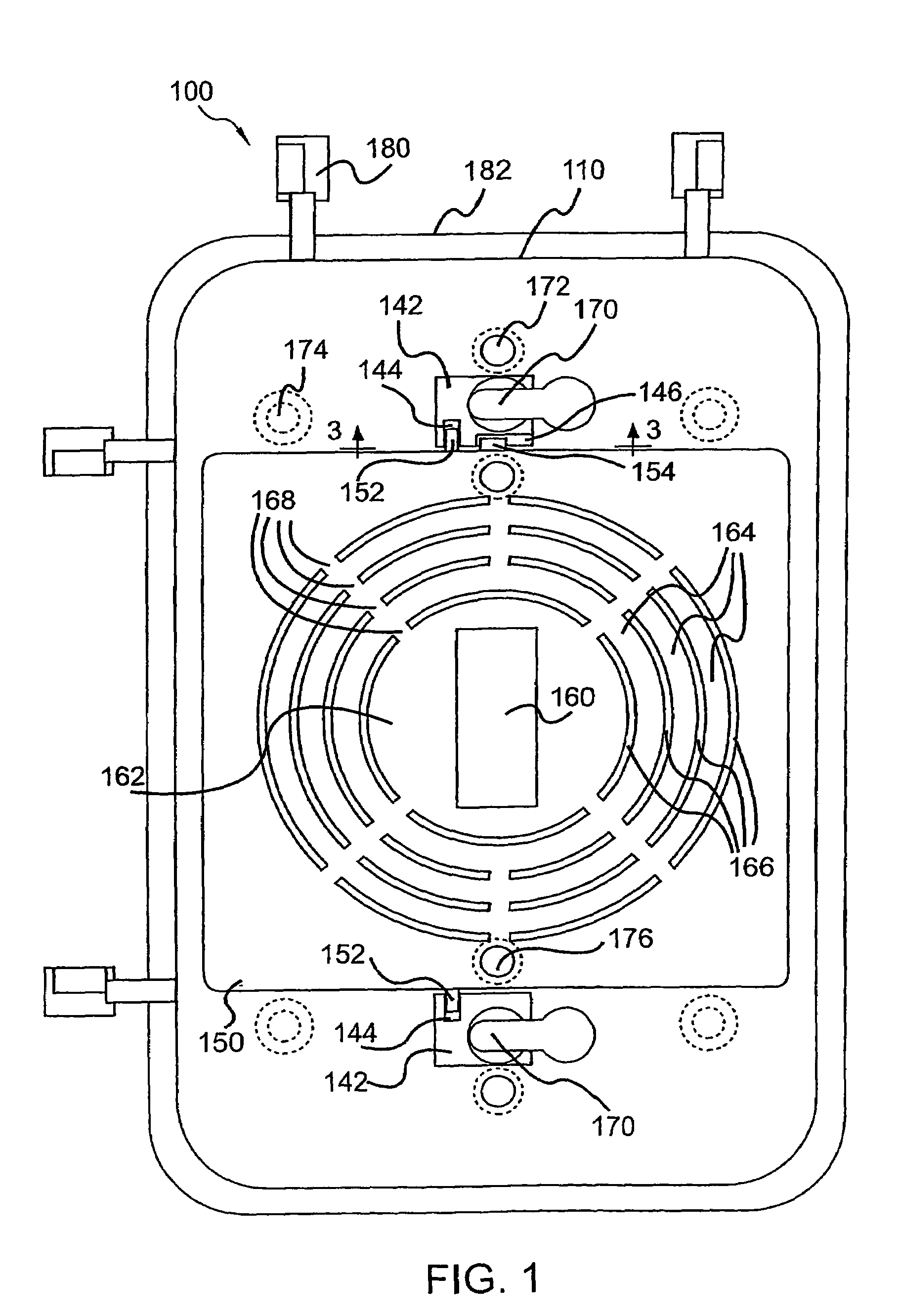
[0073]Describing the installation and use of convertible electrical device cover 100 further, a method for installing convertible electrical device cover 100 may also be provided to safely accommodate a plurality of electrical devices in a plurality of orientations. As depicted in FIGS. 8-9 for example, the installation method may include placing convertible electrical device cover 100 in an operative position over at least one electrical device so as to locate adapter plate 150 between the at least one electrical device and a rear side of base plate 110. As depicted in FIG. 9, placing the convertible electrical device cover 100 can further include holding at least one front face of the at least one electrical device at least flush with a front side of adapter plate 150, thereby ensuring a safer operating condition.

[0074]The first installation method embodiment may further include removing at least one removable tab of base plate 110, thereby converting base plate 110 to accommodate...

second embodiment

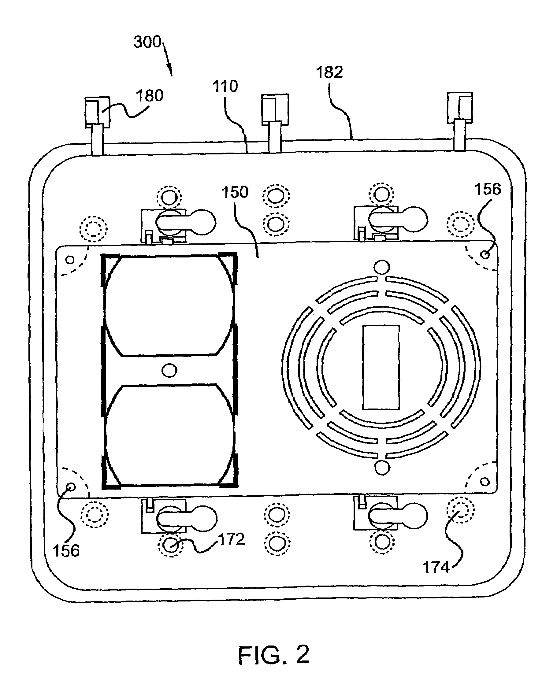
[0078]As partially depicted in FIGS. 12-13, the installation method may include: removing at least one removable tab of base plate 110 that is configured to accommodate at least one electrical device, thereby converting base plate 110 to accommodate the at least one electrical device; removing at least one removable tab of adapter plate 150 that is configured to accommodate at least one electrical device, thereby converting adapter plate 150 to accommodate the at least one electrical device; and placing convertible electrical device cover 100 in an operative position over at least one electrical device so as to locate base plate 110 between the at least one electrical device and a rear side of adapter plate 150. Placing the convertible electrical device cover 100 can further include holding at least one front face of the at least one electrical device at least flush with a front side of adapter plate 150, thereby ensuring compliance with current electrical safety standards.

[0079]Oth...


PUM


Abstract

A convertible electrical device cover including a base plate and an adapter plate configured to accommodate an electrical device. When the convertible electrical device cover is placed in an operative position over the electrical device the adapter plate may be located between the electrical device and a rear side of the base plate. A method for installing a convertible electrical device cover is also disclosed including placing the convertible electrical device cover in an operative position over an electrical device so that an adapter plate is located between the electrical device and a rear side of a base plate.

Description

[0001]This application is a continuation-in-part of the earlier patent application entitled “Convertible Electrical Device Cover and Method for Installing Same,” Ser. No. 10 / 881,288, filed Jun. 29, 2004, now U.S. Pat. No. 6,987,225 which is a continuation of the earlier patent application entitled “Convertible Electrical Device Cover and Method for Installing Same”, Ser. No. 10 / 700,737, filed Nov. 3, 2003, now U.S. Pat. No. 6,770,816, which is a continuation of an earlier patent application entitled “Convertible Electrical Device Cover and Method for Installing Same”, Ser. No. 09 / 948,920, filed Sep. 7, 2001, U.S. Pat. No. 6,642,453, the disclosures of which are hereby incorporated herein by reference.BACKGROUND OF THE INVENTION[0002]1. Technical Field[0003]This invention generally relates to covers for electrical devices, and more specifically relates to a convertible electrical device cover and method for installing same.[0004]2. Background Art[0005]Electrical devices used in conju...

Claims


Application Information

Patent Timeline
Patent Type & Authority Patents(United States)
IPC IPC(8): H02G3/14H02G3/08
CPCH02G3/14H02G3/081
Inventor MALTBY, EDGAR W.SHOTEY, MARCUS J.SHOTEY, MICHAEL J.
Owner HUBBELL INC
Why Eureka
Try Eureka