
Active dropout optimization for current mode LDOs

a current mode and dropout optimization technology, applied in the direction of power conversion systems, instruments, process and machine control, etc., can solve the problems of considerable ripple and efficiency loss of output voltage of a conventional dc/dc converter operating in a switched mode, and achieve the effect of avoiding efficiency loss

Active Publication Date: 2007-10-16
TEXAS INSTR INC
View PDF22 Cites 15 Cited by
  • Summary
  • Abstract
  • Description
  • Claims
  • Application Information

AI Technical Summary

Benefits of technology

[0003]The present invention provides a DC / DC converter with a linear regulator for reducing or eliminating the output ripple of the converter with a minimum loss of efficiency.
[0005]In a detailed implementation, the linear regulator includes a load current pass transistor in MOS technology and the tracking circuit controls the converter stage such that the voltage at the converted voltage output of the converter stage is just sufficient to avoid operation of the load current pass transistor in an unsaturated state. As a power MOS transistor has virtually no voltage loss in its saturated state, a loss of efficiency is avoided.

Problems solved by technology

The output voltage of a conventional DC / DC converter operating in a switched mode usually has a considerable ripple.
As a consequence, the load current pass transistor in the voltage regulator usually operates in an unsaturated condition, resulting in a considerable loss of efficiency.

Method used


Image

  • Active dropout optimization for current mode LDOs
  • Active dropout optimization for current mode LDOs
  • Active dropout optimization for current mode LDOs

Examples


Embodiment Construction

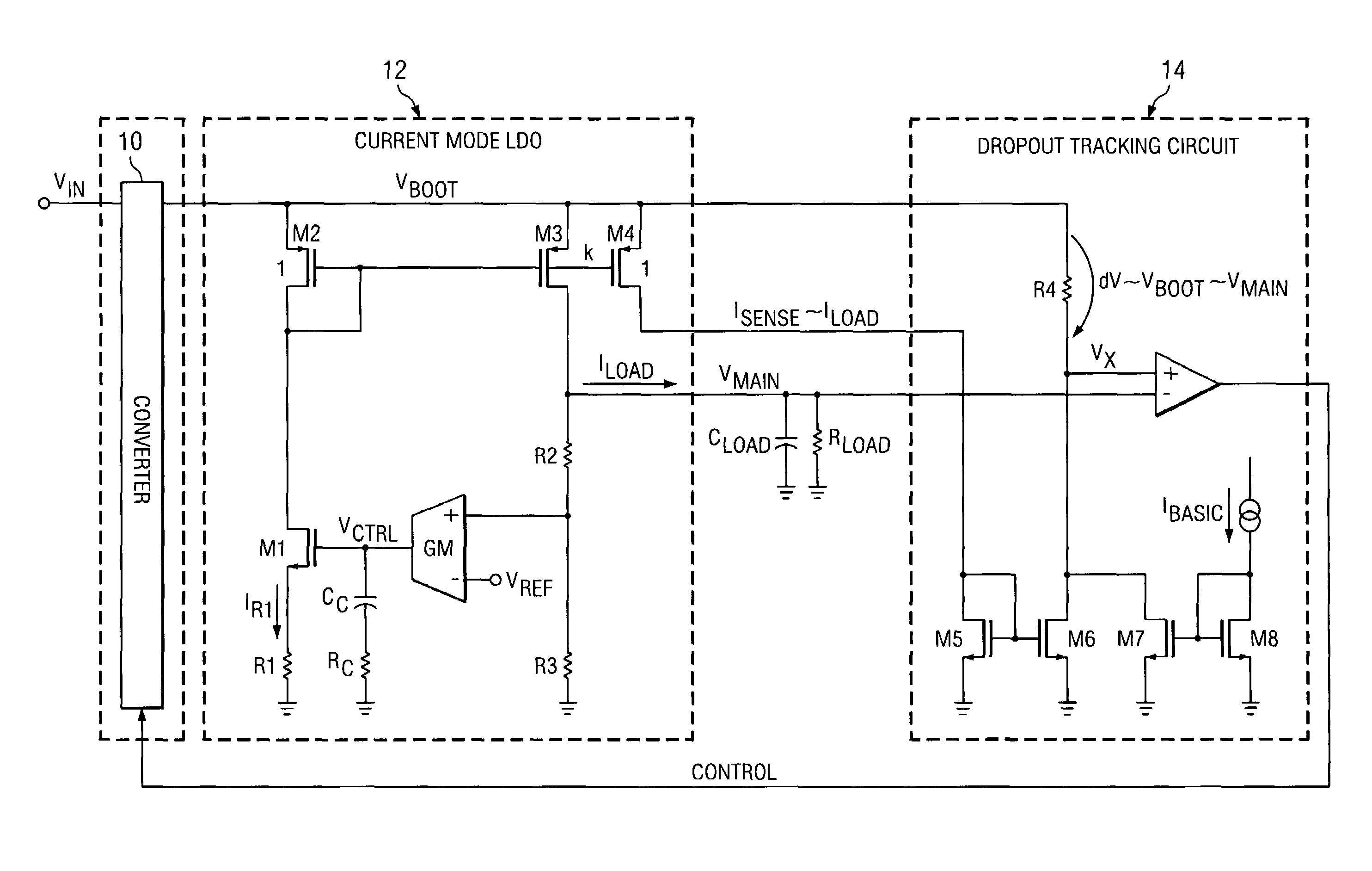
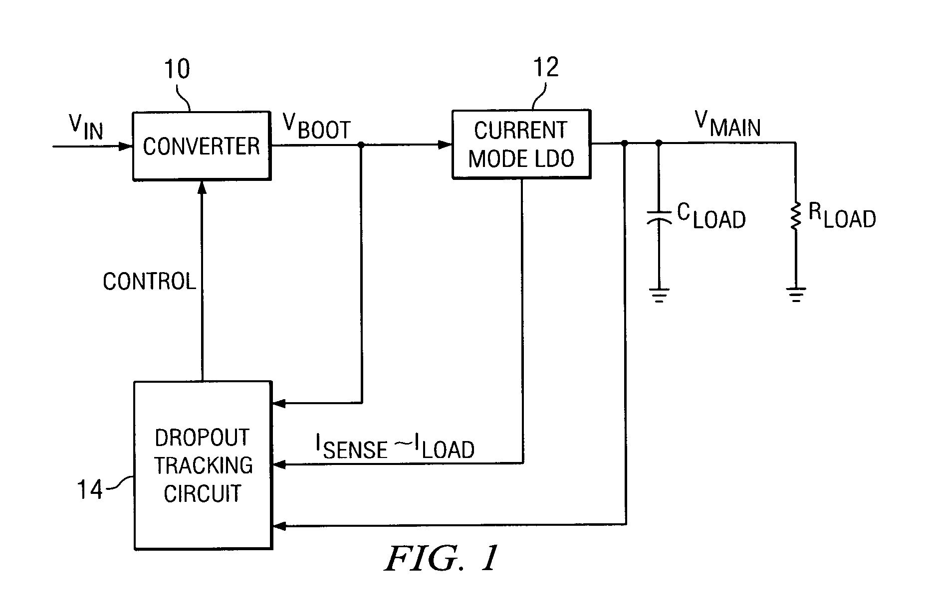
[0009]The DC / DC converter in FIG. 1 comprises a converter stage 10, a current mode LDO (Low Dropout regulator or Linear Dropout regulator) 12 and a Dropout Tracking Circuit 14. An input voltage VIN of a system is converted (by means of a Buck-, Boost-Converter, Charge Pump, or other suitable means) to a certain output converter voltage at VBOOT (see FIG. 1). A current mode LDO converts the relative high ripple voltage at VBOOT to a low ripple voltage at VMAIN. The dropout tracking circuit compares the voltages VBOOT with VMAIN and sends a Control Signal which is dependent on the load current ILOAD to the voltage converter (e.g., to change Duty Cycle of the Voltage Converter). The goal of this configuration is a low ripple output voltage VMAIN without high efficiency losses. To minimize the efficiency losses the dropout of the Linear Dropout Regulator is regulated via the dropout tracking circuit.

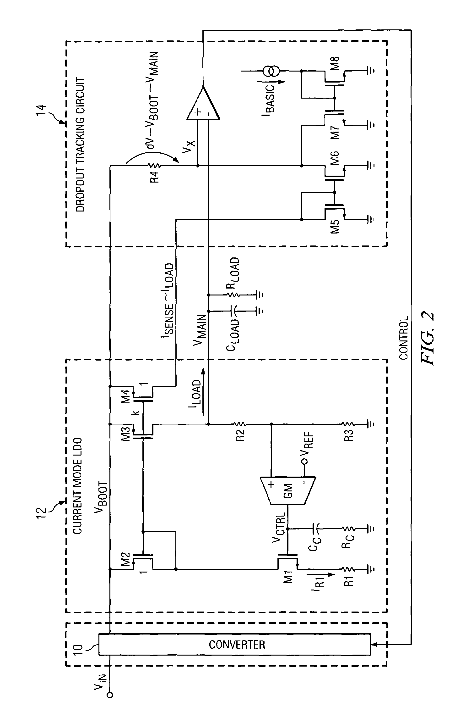
[0010]FIG. 2 shows further details of a particular implementation. In the Current Mode L...


PUM


Abstract

A DC / DC converter has a linear voltage regulator for reducing or eliminating the output ripple of the converter with a minimum loss of efficiency. The converter comprises a converter stage with a supply voltage input, a converted voltage output and a control input, a regulator stage having an input connected to the converted voltage output of the converter stage and an output connected to a load, and a tracking circuit with inputs for a voltage at the converted voltage output of the converter stage, a voltage at the output of the regulator stage and a load sense current, and an output connected to the control input of the converter stage. The tracking circuit controls the converter stage so as to increase the converted voltage with an increasing load sense current and vice versa. The output voltage of the converter is always just sufficient to eliminate the ripple without having to operate the regulator's pass transistor in its linear range.

Description

[0001]The present invention relates to a DC / DC converter with a linear regulator for reducing the output ripple of the converter.BACKGROUND OF THE INVENTION[0002]The output voltage of a conventional DC / DC converter operating in a switched mode usually has a considerable ripple. This is especially the case for converters with hysteretic control. When such ripple cannot be tolerated for a particular application, a linear regulator is inserted between the output of the converter stage and the load to eliminate the ripple. Since the voltage regulator is not aware of the load requirements, the output voltage of the converter is adjusted to a level sufficient for the regulator to eliminate the ripple under all load conditions. As a consequence, the load current pass transistor in the voltage regulator usually operates in an unsaturated condition, resulting in a considerable loss of efficiency.BRIEF SUMMARY OF THE INVENTION[0003]The present invention provides a DC / DC converter with a linea...

Claims


Application Information

Patent Timeline
Patent Type & Authority Patents(United States)
IPC IPC(8): G05F1/00G05F1/613
CPCG05F3/262H02M2001/0045H02M1/0045
Inventor THIELE, GERHARDBAYER, ERICH
Owner TEXAS INSTR INC
Learn More