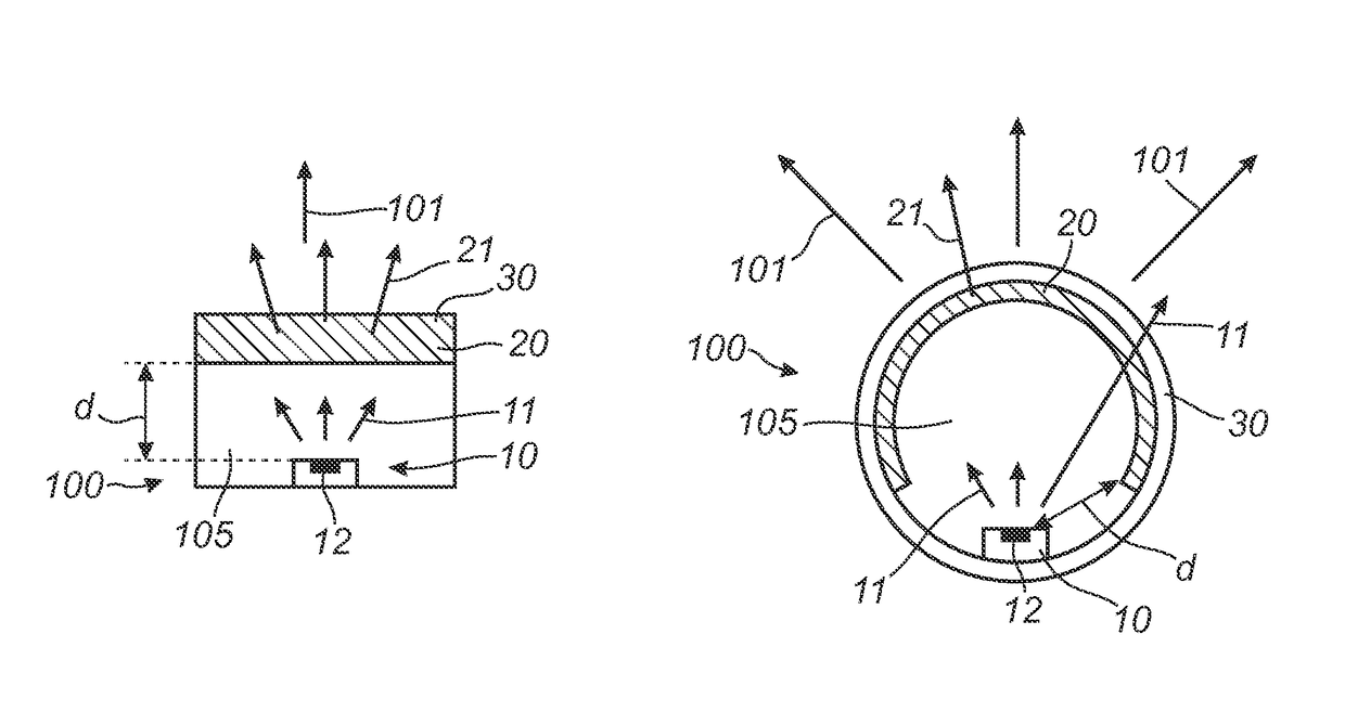
Light converter and lighting unit comprising such light converter

a technology of light converters and light converters, which is applied in the direction of lighting and heating apparatus, semiconductor devices for light sources, and light sources, etc., can solve the problems of low color rendering index (cri), low efficiency of such materials, and low price of such materials, and achieve long-term stability

Active Publication Date: 2017-04-18
SIGNIFY HLDG BV +1
View PDF34 Cites 3 Cited by
  • Summary
  • Abstract
  • Description
  • Claims
  • Application Information

AI Technical Summary

Benefits of technology

[0010]It further appears that the presence of the scattering material is beneficial. When scattering material is present, it seems to minimize the effect that the light emitted by the green phosphor is absorbed by the yellow phosphor; in other words it maximizes the effect on white emission spectrum, and therefore CRI, when replacing only a small amount of yellow phosphor by green phosphor. This is beneficial since the green phosphor is often more expensive than the yellow phosphor. Hence, it appears that the combination of at least the above mentioned four compounds may lead to light converter that can efficiently employed in a lighting unit with a blue light emitting light source to provide white light with a high CRI.
[0021]However, in addition to this green luminescent material and / or in addition to this yellow luminescent material also one or more other luminescent materials may be applied. Hence, adding LuAG is one method to increase the CRI of a (inorganic yellow+organic red) phosphor system. Any other method to reduce the cyan gap may work as well, with minimum loss of efficiency, as long as the red phosphor has a small Stokes shift (see also below). For instance, the YAG spectrum can be shifted to shorter wavelength by decreasing the Ce concentration, or by substituting Al for Ga, or a completely other type of luminescent material may be added. Hence, in an embodiment, next to Y3Al5O12:Ce3+, as yellow emitter, Y3Al4GaO12:Ce3+ may be applied.
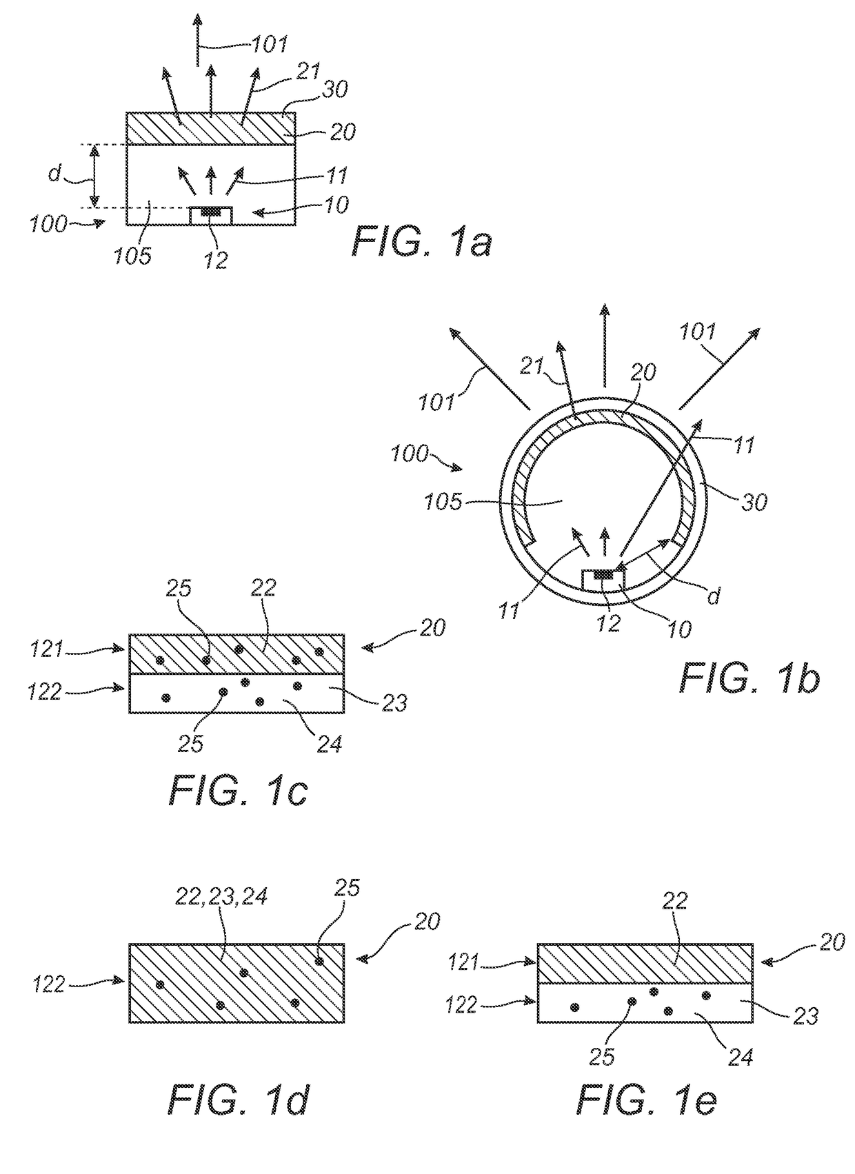
[0025]Especially advantageous appears to be embedding the organic luminescent material in a matrix, especially a polymeric matrix. Such polymeric matrix may especially be transmissive, preferably transparent. Hence, in a preferred embodiment the red light emitting organic luminescent material is embedded in a polymer matrix. Especially, the polymer matrix comprises one or more materials selected from the group consisting of PE (polyethylene), PP (polypropylene), PEN (polyethylene napthalate), PC (polycarbonate), polymethylacrylate (PMA), polymethylmethacrylate (PMMA) (PLEXIGLASS® or PERSPEX®), cellulose acetate butyrate (CAB), polyvinylchloride (PVC), polyethyleneterephthalate (PET), (PETG) (glycol modified polyethyleneterephthalate), PDMS (polydimethylsiloxane), silicone, and COC (cyclo olefin copolymer). It appears that especially a combination of (a) YAG:Ce (or small variations on the garnet material, see below), (b) a green emitting material, (c) a red light emitting organic material embedded in a polymer matrix and (d) a scattering material may provide a converter that is able to provide together with blue light, such as blue light in the range of 440-460 nm, especially 440-450 nm, light with a high CRI, higher than 80, or even higher than 85, or even of 90 or higher, with a long time stability.

Problems solved by technology

A problem of prior art systems may be that the color rendering index (CRI) is often too low.
A disadvantage however of higher wavelength blue LED's is their relatively lower efficiency.
A disadvantage may however be prices of such materials.
It surprisingly appears that very high CRI's (e.g. >90) can be obtained, by the addition of LuAG to YAG, at a very limited efficiency penalty.

Method used


Image

  • Light converter and lighting unit comprising such light converter
  • Light converter and lighting unit comprising such light converter
  • Light converter and lighting unit comprising such light converter

Examples


embodiment 1

YAG / LuAG Coated onto Polymer Film Containing Lumogen F305

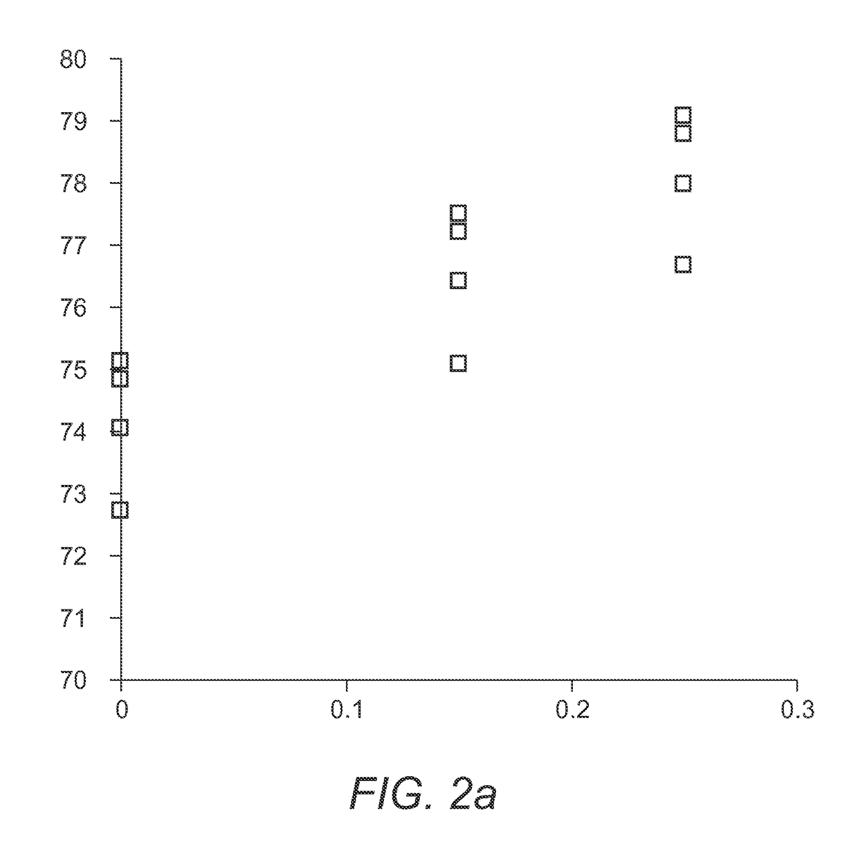
[0052]In a remote phosphor TLED a polymer film (PET) containing Lumogen F305 was used. On the foil a coating containing the inorganic garnet phosphor was applied by roll-to-roll coating. When used in combination with short wavelength LEDs (440-450 nm) replacement of ˜20 wt. % of the YAG by LuAG resulted in lamps with a CRI>80 (without LuAG the CRI was lower than 80). An additional advantage of the addition of the mixing of LuAG and YAG is the reduced shift of the color point with wavelength of the blue LED.

embodiment 2

YAG / LuAG / F305 in Polymer Film

[0053]Instead of coating the inorganic phosphors onto the polymer film, the phosphor was incorporated in the polymer using for example a film extrusion process.

embodiment 3

CRI 90 Lamp

[0054]A coating of YAG and LuAG (approximately 20 wt. % LuAG, depending on the peak wavelength of the blue LEDs used) was applied onto a PET polymer film containing F305, in which the yellow / green layer and red layer thickness were chosen such, that 2700K light will be generated, which resulted in white light with a CRI of 90 (for any LED wavelength in between 440 and 460 nm).


PUM

PropertyMeasurementUnit
CRIaaaaaaaaaa
particle sizesaaaaaaaaaa
CRIaaaaaaaaaa

Abstract

The invention provides a lighting unit having a light source, configured to generate light source light, and a light converter, configured remote of the light source and configured to convert at least part of the light source light into luminescent material light. The light converter includes (a) a yellow light emitting cerium containing garnet luminescent material, (b) a green light emitting luminescent material, (c) a red light emitting organic luminescent material, and (d) a particulate scattering material.

Description

FIELD OF THE INVENTION[0001]The invention relates to a light converter and lighting unit comprising such light converter.BACKGROUND OF THE INVENTION[0002]Lighting units comprising LED light sources and luminescent materials as light converters are known in the art.[0003]WO0108452, for instance, describes a light source comprising a radiation source having an emission from 420 to 490 nm and a phosphor having a garnet structure as represented by A3B5O12:Ce wherein A is terbium or terbium together with at least one of the elements Y, Gd, La, and / or Lu and B is at least one of the elements Al and Ga, the phosphor converting at least a part of the emission from the radiation source into a longer-wave radiation.[0004]Further, WO2010116294 describes a luminescent converter for a phosphor-enhanced light source. The luminescent converter comprises a first luminescent material configured for absorbing at least a part of excitation light emitted by a light emitter of the phosphor-enhanced ligh...

Claims


Application Information

Patent Timeline
Patent Type & Authority Patents(United States)
IPC IPC(8): F21V1/00C09K11/67F21K2/00F21K9/64C09K11/06C09K11/77H01L33/50
CPCC09K11/67C09K11/06C09K11/7721C09K11/7734C09K11/7774F21K2/00F21K9/64H01L33/504H01L33/507C09K2211/1011C09K11/02C09K11/77342
Inventor PEETERS, MARTINUS PETRUS JOSEPHWEGH, RENE THEODORUSVAN DREUMEL, GERARDUS WILHELMUS GERBE
Owner SIGNIFY HLDG BV
Why Eureka
Try Eureka