Reticulated elastomeric matrices, their manufacture and use in implantable devices

a technology of elastomeric matrices and elastomeric matrices, which is applied in the direction of prosthesis, drug compositions, transportation and packaging, etc., can solve the problems of limiting the ability of elastomeric matrices to serve as effective scaffolds, lack of mechanical properties, and unattractive biodurability of many materials produced from polyurethane foams formed by blowing during the polymerization process. achieve long-term implantation, recover

Active Publication Date: 2010-09-28
DSM SOMERSET ACQUISITION CO INC
View PDF618 Cites 61 Cited by
  • Summary
  • Abstract
  • Description
  • Claims
  • Application Information

AI Technical Summary

Benefits of technology

[0116]For treatment of orthopedic applications, it is an advantage of the invention that the implantable elastomeric matrix elements can be effectively employed without any need to closely conform to the configuration of the orthopedic application site, which may often be complex and difficult to model. Thus, in one embodiment, the implantable elastomeric matrix elements of the invention have significantly different and simpler configurations, for example, as described in the applications to which priority is claimed.
[0117]Furthermore, in one embodiment, the implantable device of the present invention, or implantable devices if more than one is used, should not completely fill the orthopedic application site even when fully expanded in situ. In one embodiment, the fully expanded implantable device(s) of the present invention are smaller in a dimension than the orthopedic application site and provide sufficient space within the orthopedic application site to ensure vascularization, cellular ingrowth and proliferation, and for possible passage of blood to the implantable device. In another embodiment, the fully expanded implantable device(s) of the present invention are substantially the same in a dimension as the orthopedic application site. In another embodiment, the fully expanded implantable device(s) of the present invention are larger in a dimension than the orthopedic application site. In another embodiment, the fully expanded implantable device(s) of the present invention are smaller in volume than the orthopedic application site. In another embodiment, the fully expanded implantable device(s) of the present invention are substantially the same volume as orthopedic application site. In another embodiment, the fully expanded implantable device(s) of the present invention are larger in volume than the orthopedic application site. In another embodiment, after being placed in the orthopedic application site the expanded implantable device(s) of the present invention may swell, e.g., by up to 1-20% in one dimension, by absorption and / or adsorption of water or other body fluids.
[0118]Some useful implantable device shapes may approximate the contour of a portion of the target orthopedic application site. In one embodiment, the implantable device is shaped as relatively simple convex, dish-like or hemispherical or hemi-ellipsoidal shape and size that is appropriate for treating multiple different sites in different patients.
[0119]It is contemplated, in another embodiment, that upon implantation, before their pores become filled with biological fluids, bodily fluids and / or tissue, such implantable devices for orthopedic applications and the like do not entirely fill, cover or span the biological site in which they reside and that an individual implanted elastomeric matrix 10 will, in many cases although not necessarily, have at least one dimension of no more than 50% of the biological site within the entrance thereto or over 50% of the damaged tissue that is being repaired or replaced. In another embodiment, an individual implanted elastomeric matrix 10 as described above will have at least one dimension of no more than 75% of the biological site within the entrance thereto or over 75% of the damaged tissue that is being repaired or replaced. In another embodiment, an individual implanted elastomeric matrix 10 as described above will have at least one dimension of no more than 95% of the biological site within the entrance thereto or over 95% of the damaged tissue that is being repaired or replaced.
[0120]In another embodiment, that upon implantation, before their pores become filled with biological fluids, bodily fluids and / or tissue, such implantable devices for orthopedic applications and the like substantially fill, cover or span the biological site in which they reside and an individual implanted elastomeric matrix 10 will, in many cases, although not necessarily, have at least one dimension of no more than about 100% of the biological site within the entrance thereto or cover 100% of the damaged tissue that is being repaired or replaced. In another embodiment, an individual implanted elastomeric matrix 10 as described above will have at least one dimension of no more than about 98% of the biological site within the entrance thereto or cover 98% of the damaged tissue that is being repaired or replaced. In another embodiment, an individual implanted elastomeric matrix 10 as described above will have at least one dimension of no more than about 102% of the biological site within the entrance thereto or cover 102% of the damaged tissue that is being repaired or replaced.
[0121]In another embodiment, that upon implantation, before their pores become filled with biological fluids, bodily fluids and / or tissue, such implantable devices for orthopedic applications and the like over fill, cover or span the biological site in which they reside and an individual implanted elastomeric matrix 10 will, in many cases, although not necessarily, have at least one dimension of more than about 105% of the biological site within the entrance thereto or cover 105% of the damaged tissue that is being repaired or replaced. In another embodiment, an individual implanted elastomeric matrix 10 as described above will have at least one dimension of more than about 125% of the biological site within the entrance thereto or cover 125% of the damaged tissue that is being repaired or replaced. In another embodiment, an individual implanted elastomeric matrix 10 as described above will have at least one dimension of more than about 150% of the biological site within the entrance thereto or cover 150% of the damaged tissue that is being repaired or replaced. In another embodiment, an individual implanted elastomeric matrix 10 as described above will have at least one dimension of more than about 200% of the biological site within the entrance thereto or cover 200% of the damaged tissue that is being repaired or replaced. In another embodiment, an individual implanted elastomeric matrix 10 as described above will have at least one dimension of more than about 300% of the biological site within the entrance thereto or cover 300% of the damaged tissue that is being repaired or replaced.

Problems solved by technology

The major weaknesses of these approaches relating to bioabsorbable three-dimensional porous scaffolds used for tissue regeneration are undesirable tissue response during the product's life cycle as the polymers biodegrade and the inability to engineer the degradation characteristics of the TE scaffold in vivo, thus severely limiting their ability to serve as effective scaffolds.
Furthermore, many materials produced from polyurethane foams formed by blowing during the polymerization process are unattractive from the point of view of biodurability because undesirable materials that can produce adverse biological reactions are generated during polymerization, for example, carcinogens, cytotoxins and the like.
A number of polymers having varying degrees of biodurability are known, but commercially available materials either lack the mechanical properties needed to provide an implantable device that can be compressed for delivery-device delivery and can resiliently expand in situ, at the intended biological site, or lack sufficient porosity to induce adequate cellular ingrowth and proliferation.
Furthermore, the final foamed polyurethane product of Brady '550 contains isocyanurate linkages and is not reticulated.
Accordingly, Brady '413 does not disclose a resiliently-compressible reticulated product or a process to make it.
The Pinchuk '330 compositions lack adequate mechanical properties to provide a compressible catheter-, endoscope-, or syringe-introducible, resilient, space-occupying porous element that can occupy a biological site and permit cellular ingrowth and proliferation into the occupied volume.
Tuch's disclosed pore sizes are too small for effective cellular ingrowth and proliferation of uncoated substrates.
Moreover, the above references do not disclose, e.g., such a device containing polycarbonate moieties.

Method used


Image

  • Reticulated elastomeric matrices, their manufacture and use in implantable devices
  • Reticulated elastomeric matrices, their manufacture and use in implantable devices
  • Reticulated elastomeric matrices, their manufacture and use in implantable devices

Examples


example 1

Fabrication of a Crosslinked Polyurethane Matrix

[0304]The aromatic isocyanate RUBINATE 9258 (from Huntsman) was used as the isocyanate component. RUBINATE 9258 is a liquid at 25° C. RUBINATE 9258 contains 4,4′-MDI and 2,4′-MDI and has an isocyanate functionality of about 2.33. A diol, poly(1,6-hexanecarbonate)diol (POLY-CD CD220 from Arch Chemicals) with a molecular weight of about 2,000 Daltons was used as the polyol component and was a solid at 25° C. Distilled water was used as the blowing agent. The blowing catalyst used was the tertiary amine triethylenediamine (33% in dipropylene glycol; DABCO 33LV from Air Products). A silicone-based surfactant was used (TEGOSTAB® BF 2370 from Goldschmidt). A cell-opener was used (ORTEGOL® 501 from Goldschmidt). The viscosity modifier propylene carbonate (from Sigma-Aldrich) was present to reduce the viscosity. The proportions of the components that were used is given in Table 2.

[0305]

TABLE 2IngredientParts by WeightPolyol Component100Viscosi...

example 2

Reticulation of a Crosslinked Polyurethane Foam

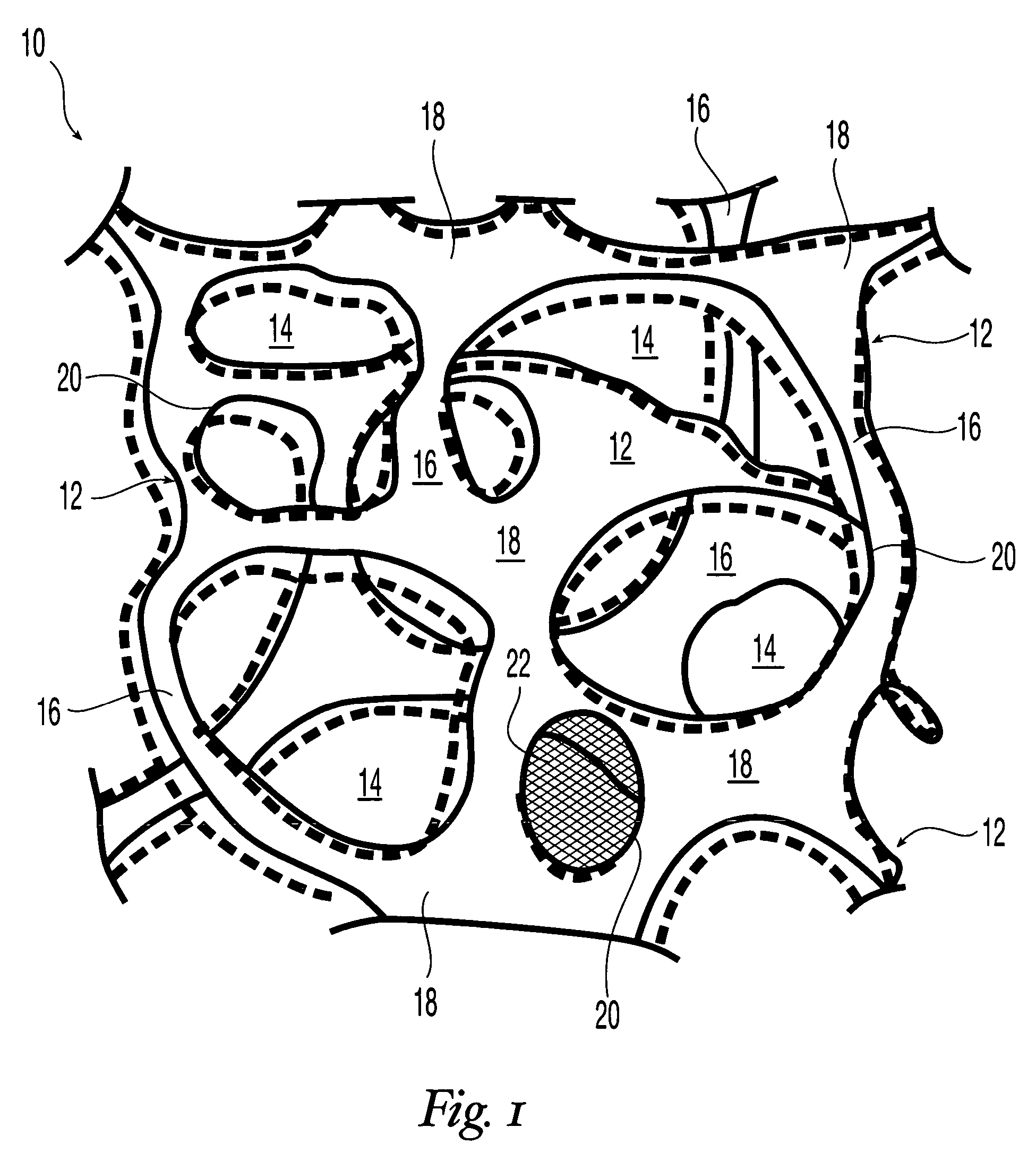
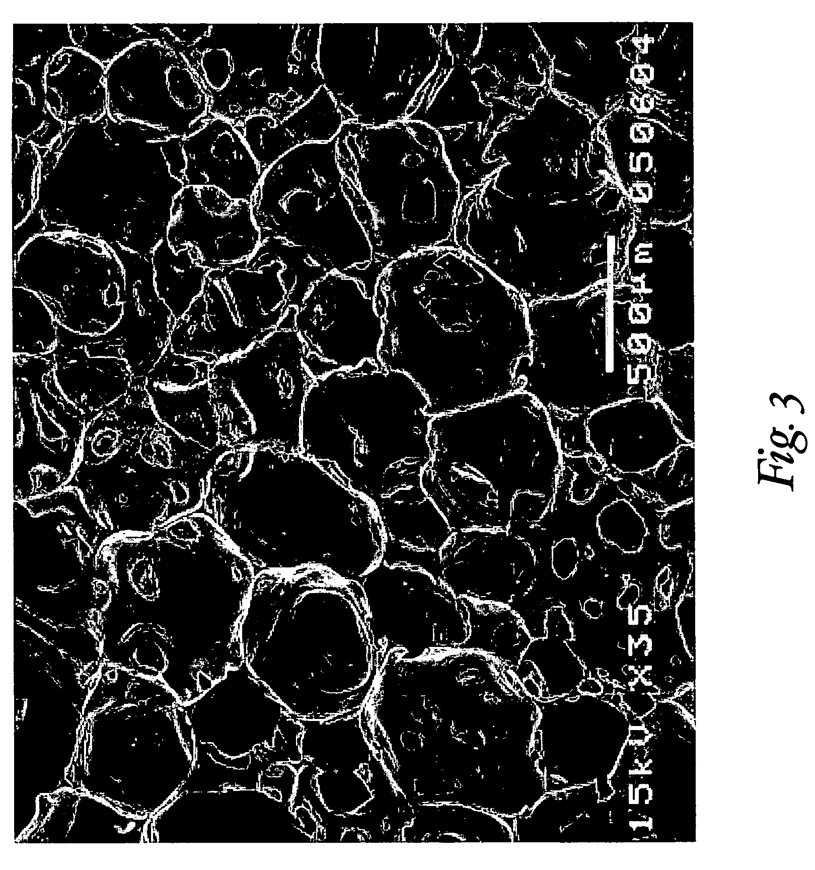
[0313]Reticulation of the foam described in Example 1 was carried out by the following procedure. A block of foam measuring approximately 15.25 cm×15.25 cm×7.6 cm (6 in.×6 in.×3 in.) was placed into a pressure chamber, the doors of the chamber were closed, and an airtight seal to the surrounding atmosphere was maintained. The pressure within the chamber was reduced to below about 100 millitorr by evacuation for at least about 2 minutes to remove substantially all of the air in the foam. A mixture of hydrogen and oxygen gas, present at a ratio sufficient to support combustion, was charged into the chamber over a period of at least about 3 minutes. The gas in the chamber was then ignited by a spark plug. The ignition exploded the gas mixture within the foam. The explosion was believed to have at least partially removed many of the cell walls between adjoining pores, thereby forming a reticulated elastomeric matrix structure.

[0314]The aver...

example 3

Fabrication of a Crosslinked Polyurethane Matrix

[0320]The components used were the same as described in Example 1. The proportions of the components that were used is given in Table 4.

[0321]

TABLE 4IngredientParts by WeightPolyol Component100Viscosity Modifier5.80Surfactant1.10Cell Opener1.00Isocyanate Component62.42Isocyanate Index1.00Distilled Water3.39Blowing Catalyst0.53

[0322]The polyol component was liquefied at 70° C. in a circulating-air oven, and 100 g thereof was weighed out into a polyethylene cup. 5.8 g of viscosity modifier was added to the polyol component to reduce the viscosity and the ingredients were mixed at 3100 rpm for 15 seconds with the mixing shaft of a drill mixer to form “Mix-1”. 1.10 g of surfactant was added to Mix-1 and the ingredients were mixed as described above for 15 seconds to form “Mix-2”. Thereafter, 1.00 g of cell opener was added to Mix-2 and the ingredients were mixed as described above for 15 seconds to form “Mix-3”. 62.42 g of isocyanate compo...


PUM

PropertyMeasurementUnit
diameteraaaaaaaaaa
diameteraaaaaaaaaa
diameteraaaaaaaaaa

Abstract

This invention relates to biodurable, reticulated elastomeric matrices that are resiliently-compressible, their manufacture and uses including uses for implantable devices into or for topical treatment of patients, such as humans and other animals, for therapeutic, nutritional, or other useful purposes.

Description

[0001]This application claims the benefit of U.S. provisional application No. 60 / 471,518, filed May 15, 2003, and International Application no. PCT / US03 / 33750, filed Oct. 23, 2003, the disclosure of each application being incorporated by reference herein in its entirety.FIELD OF THE INVENTION[0002]This invention relates to reticulated elastomeric matrices, their manufacture and uses including uses for implantable devices into or for topical treatment of patients, such as humans and other animals, for therapeutic, nutritional, or other useful purposes. For these and other purposes the inventive products may be used alone or may be loaded with one or more deliverable substances.BACKGROUND OF THE INVENTION[0003]The tissue engineering (“TE”) approach generally includes the delivery of a biocompatible tissue substrate that serves as a scaffold or support onto which cells may attach, grow and / or proliferate, thereby synthesizing new tissue by regeneration or new tissue growth to repair a ...

Claims


Application Information

Patent Timeline
Patent Type & Authority Patents(United States)
IPC IPC(8): A61K9/22A61FA61F2/28
CPCA61L27/18A61L27/48A61L27/56C08L75/04C08L89/06Y10T428/24512Y10T428/31551A61P43/00
Inventor DATTA, ARINDAMFRIEDMAN, CRAIGKLEMPNER, DANIELSENDIJAREVIC, AISA
Owner DSM SOMERSET ACQUISITION CO INC
Why Eureka
Try Eureka