Reticulated elastomeric matrices, their manufacture and use in implantable devices

a technology of elastomeric matrices and matrices, which is applied in the field of reticulated elastomeric matrices, can solve the problems of lack of mechanical properties, unattractive known processes, and no known implantable device has been specifically designed or available, and achieves the effects of regaining shape and most of its size, long-term implantation, and sufficient porosity

Inactive Publication Date: 2010-09-30
BIOMERIX CORP
View PDF7 Cites 46 Cited by
  • Summary
  • Abstract
  • Description
  • Claims
  • Application Information

AI Technical Summary

Benefits of technology

[0126]For treatment of vascular malformations, it is an advantage of the invention that the implantable elastomeric matrix elements can be effectively employed without any need to closely conform to the configuration of the vascular malformation, which may often be complex and difficult to model. Thus, in one embodiment, the implantable elastomeric matrix elements of the invention have significantly different and simpler configurations, for example, as described in the copending applications.
[0127]Furthermore, in one embodiment, the implantable device of the present invention, or implantable devices if more than one is used, should not completely fill the aneurysm or other vascular malformation even when fully expanded in situ. In one embodiment, the fully expanded implantable device(s) of the present invention are smaller in a dimension than the vascular malformation and provide sufficient space within the vascular malformation to ensure vascularization, cellular ingrowth and proliferation, and for passage of blood to the implantable device. In another embodiment, the fully expanded implantable device(s) of the present invention are substantially the same in a dimension as the vascular malformation. In another embodiment, the fully expanded implantable device(s) of the present invention are larger in a dimension than the vascular malformation. In another embodiment, the fully expanded implantable device(s) of the present invention are smaller in volume than the vascular malformation. In another embodiment, the fully expanded implantable device(s) of the present invention are substantially the same volume as the vascular malformation. In another embodiment, the fully expanded implantable device(s) of the present invention are larger in volume than the vascular malformation.
[0128]Some useful implantable device shapes may approximate a portion of the target vascular malformation. In one embodiment, the implantable device is shaped as relatively simple convex, dish-like or hemispherical or hemi-ellipsoidal shape and size that is appropriate for treating multiple different sites in different patients.
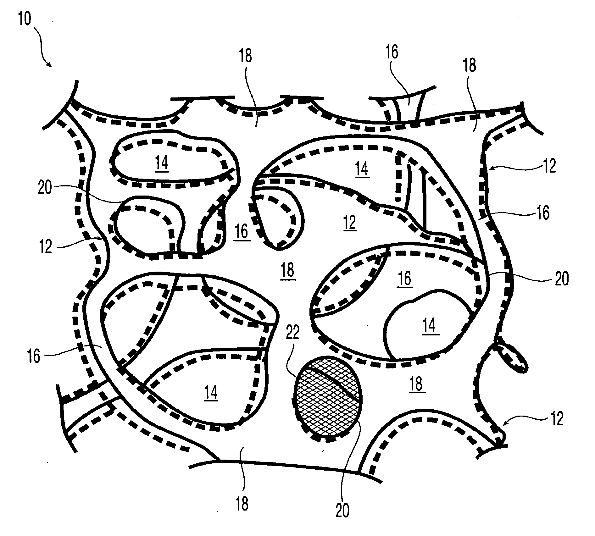
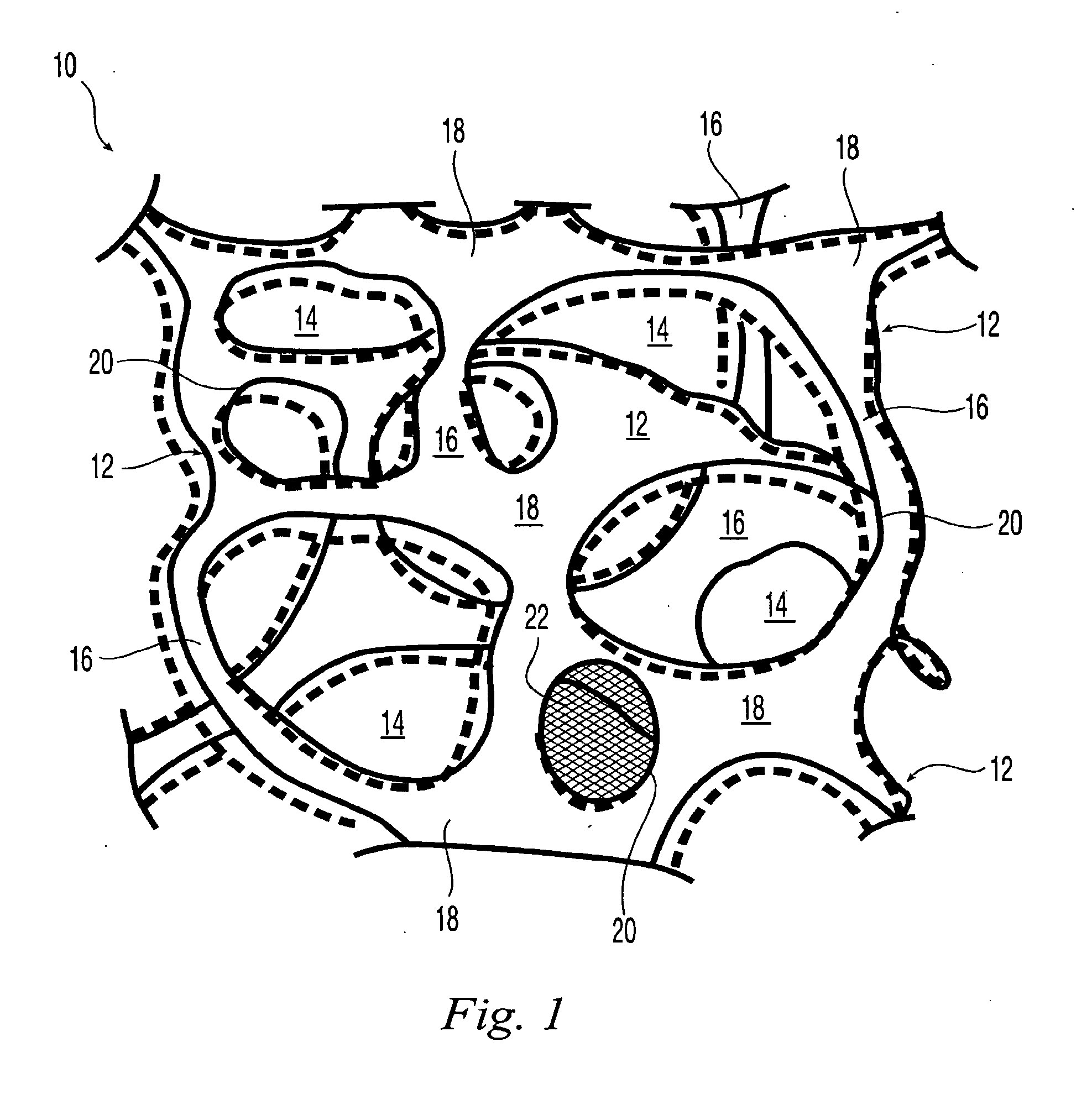
[0129]It is contemplated, in another embodiment, that even when their pores become filled with biological fluids, bodily fluids and / or tissue in the course of time, such implantable devices for vascular malformation applications and the like do not entirely fill the biological site in which they reside and that an individual implanted elastomeric matrix 10 will, in many cases, although not necessarily, have a volume of no more than 50% of the biological site within the entrance thereto. In another embodiment, an individual implanted elastomeric matrix 10 will have a volume of no more than 75% of the biological site within the entrance thereto. In another embodiment, an individual implanted elastomeric matrix 10 will have a volume of no more than 95% of the biological site within the entrance thereto.
[0130]In another embodiment, when their pores become filled with biological fluids, bodily fluids and / or tissue in the course of time, such implantable devices for vascular malformation applications and the like substantially fill the biological site in which they reside and an individual implanted elastomeric matrix 10 will, in many cases, although not necessarily, have a volume of no more than about 100% of the biological site within the entrance thereto. In another embodiment, an individual implanted elastomeric matrix 10 will have a volume of no more than about 98% of the biological site within the entrance thereto. In another embodiment, an individual implanted elastomeric matrix 10 will have a volume of no more than about 102% of the biological site within the entrance thereto.
[0131]In another embodiment, when their pores become filled with biological fluids, bodily fluids and / or tissue in the course of time, such implantable devices for vascular malformation applications and the like over-fill the biological site in which they reside and an individual implanted elastomeric matrix 10 will, in many cases, although not necessarily, have a volume of more than about 105% of the biological site within the entrance thereto. In another embodiment, an individual implanted elastomeric matrix 10 will have a volume of more than about 125% of the biological site within the entrance thereto. In another embodiment, an individual implanted elastomeric matrix 10 will have a volume of more than about 150% of the biological site within the entrance thereto.

Problems solved by technology

Although porous implantable products are known that are intended to encourage tissue invasion in vivo, no known implantable device has been specifically designed or is available for the specific objective of being compressed for a delivery-device, e.g., catheter, endoscope or syringe, delivery to a biological site, being capable of expanding to occupy and remain in the biological site and being of a particular pore size such that it can become ingrown with tissue at that site to serve a useful therapeutic purpose.
In general such known processes are unattractive from the point of view of biodurability because undesirable materials that can produce adverse biological reactions are generated, for example carcinogens, cytotoxins and the like.
A number of polymers having varying degrees of biodurability are known, but commercially available materials either lack the mechanical properties needed to provide an implantable device that can be compressed for delivery-device delivery and can resiliently expand in situ, at the intended biological site, or lack sufficient porosity to induce adequate cellular ingrowth and proliferation.
Greene's hydrogel lacks the mechanical properties to enable it to regain its size and shape in vivo were it to be compressed for catheter, endoscope or syringe delivery.
Furthermore, the final foamed polyurethane product of Brady '550 contains isocyanurate linkages and is not reticulated.
Accordingly, Brady '413 does not disclose a resiliently-compressible reticulated product or a process to make it.
Additionally, Gilson's open cell foam is not reticulated.
The Pinchuk '330 compositions may lack adequate mechanical properties to provide a compressible catheter-, endoscope-, or syringe-introducible, resilient, space-occupying porous element that can occupy a biological site and permit cellular ingrowth and proliferation into the occupied volume.
Rosenbluth does not disclose, e.g., polycarbonate polyurethane foams.
Additionally, Rosenbluth's polymer foam is not reticulated.
Further, Ma does not disclose a resiliently-compressible product.
Moreover, the above references do not disclose, e.g., such a device containing polycarbonate moieties.

Method used


Image

  • Reticulated elastomeric matrices, their manufacture and use in implantable devices
  • Reticulated elastomeric matrices, their manufacture and use in implantable devices
  • Reticulated elastomeric matrices, their manufacture and use in implantable devices

Examples


example 1

Fabrication of a Polycarbonate Polyurethane Matrix by Sacrificial Molding

[0333]As shown in FIG. 4, a substrate was prepared by fusing together particles 80, e.g., under modest temperature and pressure, spherical waxy particles 80 formed of e.g., VYBAR® 260 hydrocarbon polymer obtained from Baker Petrolite (Sugar Land, Tex.). Particles 80 were screened to a relatively narrow diameter distribution, about 3 mm to about 5 mm in diameter, before use. About 20 mL of the screened particles were poured into a transparent 100 mL polypropylene disposable beaker with a perforated bottom, i.e., vessel 82, to provide a compact three-dimensional mass with significant height in the beaker. The beaker was placed into a sealant sleeve attached to a buchner flask which was, in turn, attached to a low-pressure source.

[0334]A pressure of about 3-5 psi (about 2,100-3,500 kg / m2) was applied to wax particles 80 by employing a weight W supported on a load-spreading plate 84 resting on the wax particles so ...

example 2

Fabrication of a Polycarbonate Polyurethane Matrix by Sacrificial Molding

[0340]Example 1 is thrice repeated, each time employing smaller particles, i.e., having average sizes of 1.5, 1 and 0.5 mm, respectively. Results comparable to Example 1 are obtained in each case.

example 3

Fabrication of a Polycarbonate Polyurethane Matrix by Sacrificial Molding Alternative Method

[0341]A solution of BIONATE® 80A in THF was made according to Example 1 except that its concentration was 7% by weight of the polycarbonate polyurethane polymer. As also described in Example 1, VYBAR 260 hydrocarbon polymer particles were used except that the particles were screened to a relatively narrow diameter distribution, about 1 mm to about 2 mm in diameter, before use.

[0342]As described in Example 1, about 20 mL of the 7% polymer solution was poured onto the top layer of the wax particles. However, in this example, the wax particles in the beaker were neither heated nor compressed before being contacted by the solution. A reduced pressure of about 5 inches of mercury was applied to the buchner flask. As soon as the polymer solution was drawn down into the wax particles, an additional 20 mL of particles was poured onto the upper layer of the scaffold and a load-spreading plate slightly...


PUM


Abstract

This invention relates to biodurable, reticulated elastomeric matrices that are resiliently-compressible, their manufacture and uses including uses for implantable devices into or for topical treatment of patients, such as humans and other animals, for therapeutic, nutritional, or other useful purposes.

Description

[0001]This application is a continuation of a U.S. non-provisional application Ser. No. 10 / 749,742, filed Dec. 30, 2003, which claims the benefit of U.S. provisional application No. 60 / 437,955, filed Jan. 3, 2003, U.S. provisional application No. 60 / 471,520, filed May 15, 2003, and International Application no. PCT / US03 / 33750, filed Oct. 23, 2003, the disclosure of each application being incorporated by reference herein in its entirety.FIELD OF THE INVENTION[0002]This invention relates to reticulated elastomeric matrices, their manufacture and uses including uses for implantable devices into or for topical treatment of patients, such as humans and other animals, for therapeutic, nutritional, or other useful purposes. For these and other purposes the inventive products may be used alone or may be loaded with one or more deliverable substances.BACKGROUND OF THE INVENTION[0003]Although porous implantable products are known that are intended to encourage tissue invasion in vivo, no know...

Claims


Application Information

Patent Timeline
Patent Type & Authority Applications(United States)
IPC IPC(8): A61F2/06B29C41/00B29C41/42B29C44/00B05D7/02C08G18/08A61F2/00A61L27/18A61L27/50A61L27/56
CPCA61F2/0077A61L27/18A61L27/50A61L27/56C08L75/04
Inventor DATTA, ARINDAMFRIEDMAN, CRAIGCOSTANTINO, PETER D.ASKILL, IAN N.KLEMPNER, DANIELTINKELENBERG, ARTHUR H.SENDIJAREVIC, AISA
Owner BIOMERIX CORP
Why Eureka
Try Eureka