Optically-pumped DUV atomic vapor lasers

a laser and atom vapor technology, applied in the field of deep ultraviolet (duv) lasers, can solve the problems of adding complexity and expense to exposure lasers, increasing the cost of ownership of lithographic exposure sources, and two-photon optical damage in optical elements

Inactive Publication Date: 2007-10-16
KRUPKE WILLIAM F
View PDF3 Cites 12 Cited by
  • Summary
  • Abstract
  • Description
  • Claims
  • Application Information

AI Technical Summary

Benefits of technology

[0019]An object of the present invention is to provide a novel means of creating a steady-state population inversion density between the 1P1 excited levels and the 1S0 ground level of each of the group IIB atoms.
[0020]An object of the present invention is to provide a novel means of creating a repetitive transient population inversion density between the 1P1 excited levels and the 1S0 ground level of each of the group IIB atoms.
[0024]In a mercury OPAVL, radiation at wavelengths of 253.7 nm and 404.8 nm from two pump lasers is directed into the gain cell, and is absorbed by the mercury vapor in a two-step incoherent energy-summing process. This two step excitation process generates a first population inversion and laser oscillation on the 1207 nm transition between the 6s 7s 3S1 and 6s 6p 1P1 levels (designated the internal “idler” laser transition); this laser oscillation, in turn, generates a second population inversion between the 6s 6p 1P1 level and the 6s2 1S0 ground level of the mercury atom, resulting in laser action and generation of DUV-OPAVL output power at 185.0 nm in the 6s 6p 1P1−6s2 1S0 resonance transition.

Problems solved by technology

The high peak intensity of these illumination sources can cause two-photon optical damage in optical elements of the lithographic imaging system.
In the case of the KrF and ArF excimer lasers, additional optical elements must be included in the laser resonator to effectively narrow the line-width of the output radiation, adding complexity and expense to these exposure lasers.
Additionally, these excimer lasers require the use of corrosive and potentially dangerous halogen gases, also increasing the cost of ownership of these lithographic exposure sources.
Generally, sub-250 nm laser transitions take place in the rare gas ions so that these lasers are generally quite inefficient (<<1%), are bulky, and require expensive power conditioning equipment More recently, sub-250 nm laser sources have been produced using non-linear conversion processes to convert radiation from a “drive” laser emitting at longer wavelengths into the shorter wavelength region.
At such intensities, nonlinear optical materials tend to degrade due to optical damage.
Thus, sub-250 nm lasers produced using a nonlinear material to generate sub-250 nm radiation are not reliable, and complicated and expensive defensive measures must be adopted, such as periodically translating the nonlinear optical crystal transversely to the drive laser input beam to operate in an undamaged region of the crystal.
While the optical damage problem of solid nonlinear optical materials is avoided, realization of efficient continuous-wave operation is generally precluded (as is operation even with low peak-power pulses and many tens of kHz pulse repetition rate).
While providing adequate power and spectral brightness, argon ion lasers are extremely inefficient (<0.01%), require extensive conditioned electrical power and active cooling, and are physically bulky.
The stressing operating conditions within an argon laser generally limit the operating lifetime of a typical argon ion laser tube to <10,000 hours.
In attempts to utilize these crystals at even shorter wavelengths, problems with conversion efficiency and operating lifetime decreases substantially due to a narrowing between the required drive intensity for practical conversion efficiency and the threshold intensity for optical damage.
Because of the very low efficiency of the argon ion laser, this laser scheme is not regarded as practical for commercial use.
The cost and performance of this type of source is burdened by the requirements of phase-matching all drive and output waves (in resonant optical cavities) and optical damage in CLBO at wavelength below 200 nm.

Method used


Image

  • Optically-pumped DUV atomic vapor lasers
  • Optically-pumped DUV atomic vapor lasers
  • Optically-pumped DUV atomic vapor lasers

Examples


Embodiment Construction

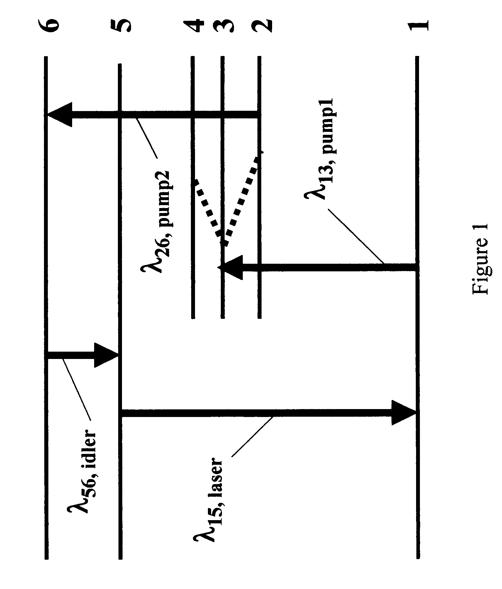
[0038]FIG. 1 shows the working energy level scheme of a group IIB atomic vapor medium used in the DUV-OPAVL. Six primary electronic levels are depicted, labeled 1 through 6. Initially the atomic vapor is quiescent and all vapor atoms reside in the ground level, labeled 1. The radiation from a first “drive” or pump laser whose output wavelength, λ13,pump1, substantially matching that of the atomic vapor transition labeled 1–3 is propagated into the vapor, exciting vapor atoms from the ground level 1 to the level labeled 3. With an appropriate buffer gas or a mixture of buffer gases, such as helium and nitrogen, mixed in with the atomic vapor, the electron population excited into level 3 will redistribute into the adjacent energy levels labeled 2 and 4 upon collisions with the buffer gas atoms and / or molecules, approaching a Boltzmann population distribution among levels 2, 3, and 4 characterized by a temperature substantially equal to the buffer gas translational temperature. The con...


PUM


Abstract

Optically-pumped group IIB atomic vapor lasers emitting at discrete wavelengths shorter than 230 nm are disclosed. This laser device utilizes an active medium comprising a mixture of a group IIB atomic vapor and one or more buffer gases placed within a doubly-resonant optical cavity that enables the realization of a population inversion between the first 1P1 level and the 1S0 ground level of the group IIB atoms. The laser may operate in a pure continuous-wave mode, or in a high-repetition pulsed mode, at DUV wavelengths of ˜185 nm (mercury), ˜229 nm (cadmium) and ˜214 nm (zinc).

Description

[0001]This application claims priority to U.S. Provisional Patent Application Ser. No. 60 / 480,771, filed Jun. 24, 2003, titled: “OPTICALLY-PUMPED 185.0 NM MERCURY VAPOR LASER,” incorporated herein by reference.BACKGROUND OF THE INVENTION[0002]1. Field of the Invention[0003]The present invention relates generally to deep ultraviolet (DUV) lasers, and more specifically, it relates to DUV optically-pumped atomic vapor lasers (DUV-OPAVLs).[0004]2. Description of the Related Art[0005]As the feature size of silicon microelectronic integrated circuits (ICs) continues to decline in the quest for ever-higher speeds (from˜a micron five years ago to a projected ˜0.1 micron in the next few years), there continues to be an urgent need for practical laser sources with progressively shorter operating wavelengths from the present main production operating wavelength of 248 nm, and beyond the emergent advanced production operating wavelength of 193 nm. Such sources are needed to: 1) provide exposure...

Claims


Application Information

Patent Timeline
Patent Type & Authority Patents(United States)
IPC IPC(8): H01S3/227H01S3/094H01S3/0943H01S3/16H01S3/22H01S3/23
CPCH01S3/0943H01S3/227H01S3/094092H01S3/2383H01S3/1643H01S3/1611
Inventor KRUPKE, WILLIAM F.
Owner KRUPKE WILLIAM F
Why Eureka
Try Eureka