

Oxygen sensor for aircraft fuel inerting systems
a fuel inerting system and oxygen sensor technology, applied in the direction of instruments, scientific instruments, measurement devices, etc., can solve the problem of potentially dangerous fuel-air mixtures
- Summary
- Abstract
- Description
- Claims
- Application Information
AI Technical Summary
Benefits of technology
Problems solved by technology
Method used
Image

Examples
Embodiment Construction
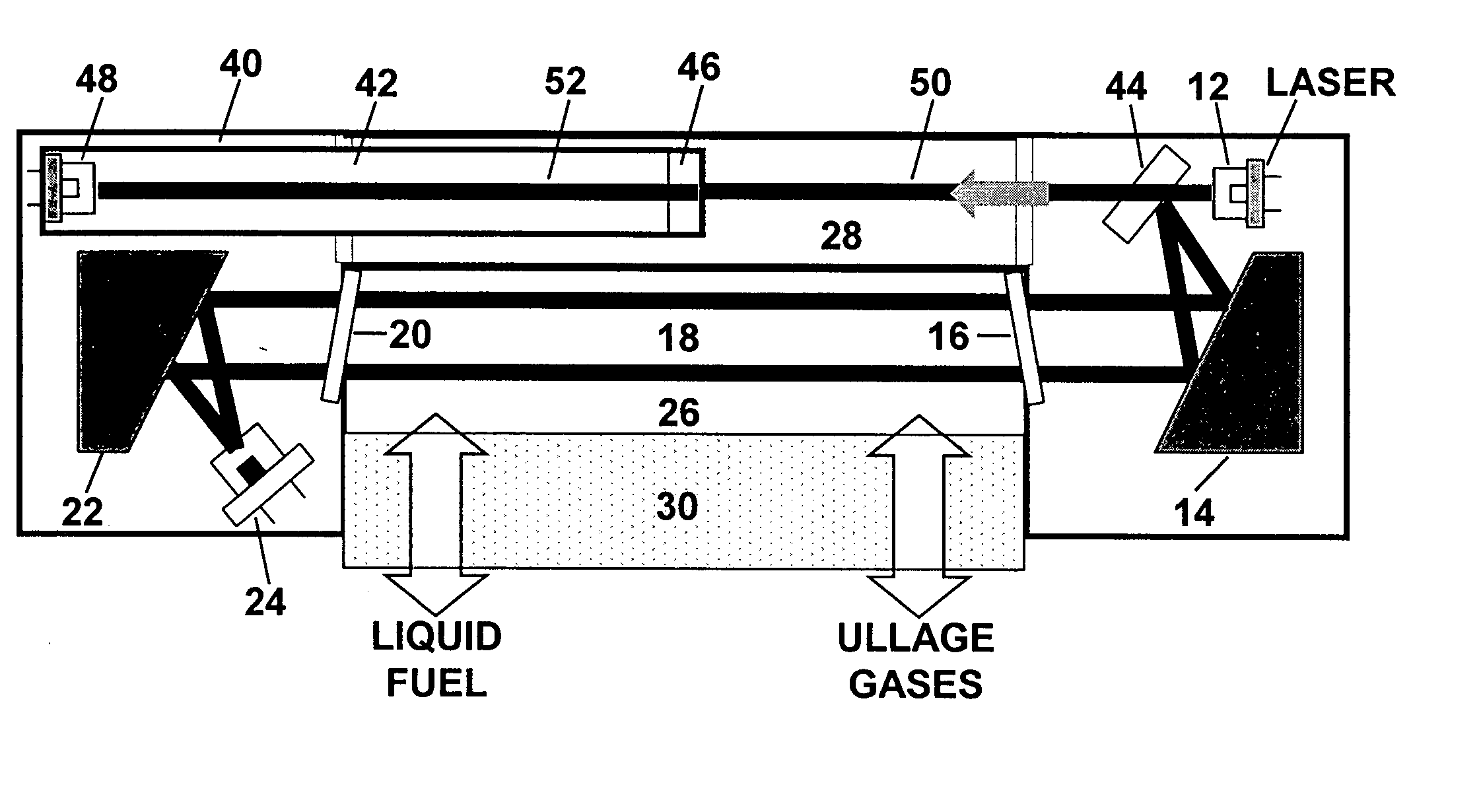
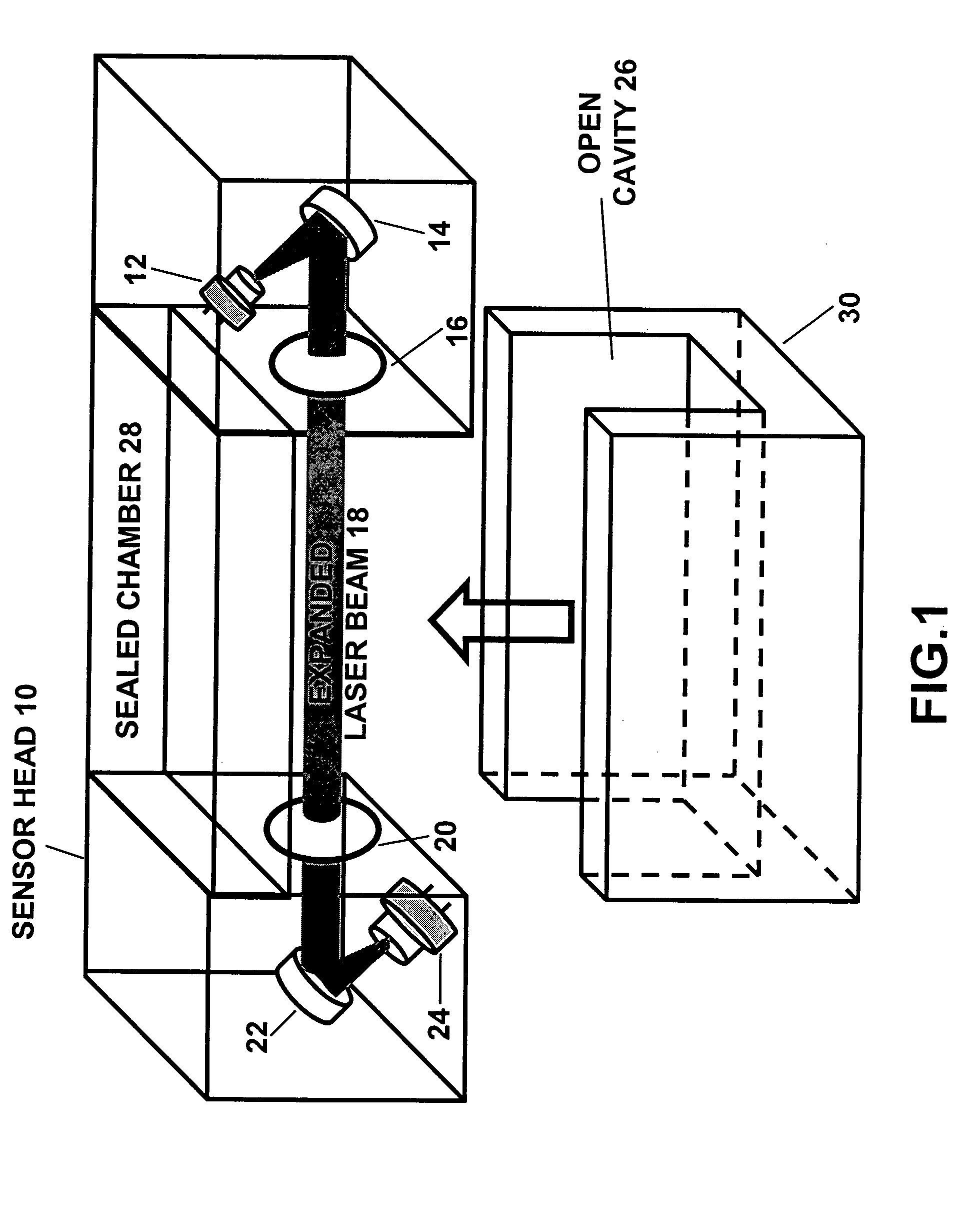
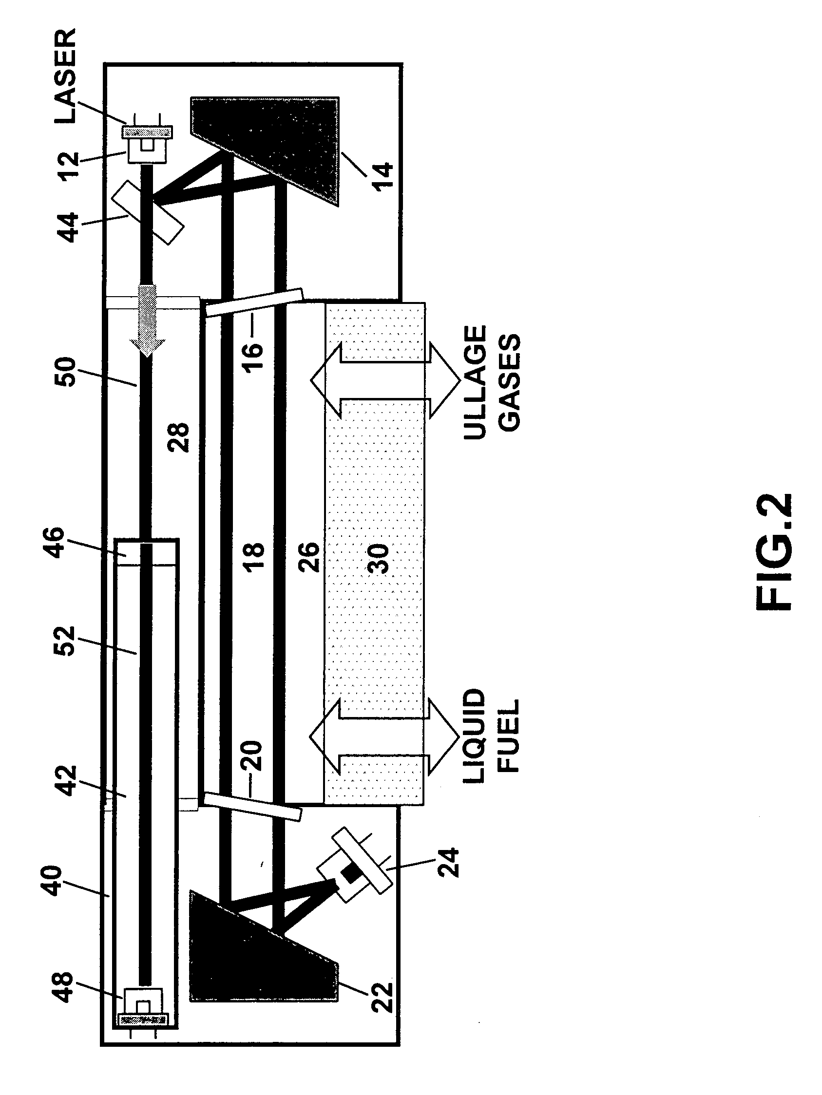
[0024] The present invention is of a sensor system that can continuously monitor oxygen concentrations in aircraft fuel inerting systems which comprise an on-board inert gas generation system and fuel tank. The oxygen sensor system preferably comprises: a sensor head that is inside the fuel tank or in-line with the ASM outlet to monitor oxygen concentrations; an electronics module for controlling the sensor head, acquiring and processing data; and a reporting mechanism for visual and audible warnings to the pilot and a feedback control parameter to the inerting system. The invention can monitor oxygen concentrations inside the ullage of aircraft fuel tanks and / or in-line at the outlet of an air separation module for an onboard inert gas generation system, without the need of a reference cell, with a measurement cavity that is open to the environment being measured, with means to minimize optical degradation due to splashing liquid fuel and liquid droplets depositing on optical windo...
PUM
| Property | Measurement | Unit |
|---|---|---|
| frequencies | aaaaa | aaaaa |
| wavelengths | aaaaa | aaaaa |
| wavelengths | aaaaa | aaaaa |
Abstract
Description
Claims
Application Information