Methods and apparatus for advanced wind turbine design

a technology of advanced wind turbines and wind turbines, applied in the direction of electric generator control, fluid couplings, greenhouse gas reduction, etc., can solve the problems of loss of energy, cost, complexity, and complexity of conversion stages to achieve the effect of slowing down the pressure level of high pressure tanks

Active Publication Date: 2007-02-27
MCCLINTIC FRANK
View PDF13 Cites 96 Cited by
  • Summary
  • Abstract
  • Description
  • Claims
  • Application Information

AI Technical Summary

Benefits of technology

[0009]One feature of various embodiments of the present invention is that the wind turbine system includes a wind turbine blade assembly which is coupled to a hydraulic pump, e.g., directly, thru a gearbox, or thru a transmission assembly. In some such embodiments, the tower upon which the wind turbine blade assembly and / or hydraulic pump is mounted is a hollow tower, e.g. metallic steel chamber, which includes a high pressure vessel into which the wind turbine driven hydraulic pump sends the pressurized hydraulic fluid to the high pressure vessel, e.g., reservoir. The pressure vessel may be an integral part of the tower support structure. The tower can also include a low pressure feed reservoir, e.g., in its base. In some embodiments, the low pressure feed reservoir may be part of a separate structure, e.g., a base structure or an in-ground tank. The low pressure inlet side of the hydraulic pump can be fed from the low pressure tank via a feed tube which is located internal to or adjacent to the tower. The high-pressure fluid output from the hydraulic pump is used to power a hydraulic motor, which is coupled to an electric generator. A hydraulic proportional control valve controls the speed / rpm at which hydraulic motor is turned which in turn controls the speed / rpm at which the generator is turned. Operating under the direction of a computer control module processing input from sensors, the proportioning control valve is computer controlled so that the frequency of the generated electricity will match the grid frequency specifications thus making the generated power directly usable and eliminating the need for invertors or other electronic means to convert the generated power signals to the grid frequency.
[0010]In accordance with some embodiments of the present invention, the volume of high pressure tank is such that the process described above will allow for the storage of energy, e.g., excess capacity energy, in the high pressure tank such that operation of the hydraulic motor, and the generation of electricity can continue for an extended period of time after the wind turbine blades have stopped spinning, e.g., due to insufficient wind speed. The hydraulic motor continues to operate driving the generator and generating electricity while the pressure level in the high pressure tank slowly decreases. This feature of the present invention allows the output of power from the wind turbine system for some time after the wind sensor will have notified the grid of an impending loss of power do to high or low wind velocity. This extended time period of electrical output allows for notification to the grid of a power generation loss in that the wind turbine system, which has now become an energy storage medium which is being depleted. This early notification feature allows for the power grid management system to accommodate for an impending loss of wind source power onto the grid by preparing to adjust other power sources, e.g. fossil fuel power source, output levels. The wind turbine system can, and in various embodiments does, notify the power management system in advance of the point in time when the wind turbine system will cut off the electrical output to the grid. The wind turbine system can, and in various embodiments does, notify the power management system in advance of the point in time when the wind turbine system will reconnect to the grid to deliver energy.
[0011]In accordance with another feature of various embodiments of the present invention, the stored energy in the form of hydraulic pressure is allowed to be reduced to a point, but not beyond such a point, where the sensors indicate that there is enough reserve capacity left in the pressurized hydraulic fluid such that a restart the wind turbine. Then when wind conditions permit restarting of the turbine is implemented by using the remaining hydraulic pressure to restart the hydraulic pump and start the turbine blade assembly spinning. This approach of the present invention of using stored hydraulic pressure to restart the wind turbine removes the load demands typically placed on the power grid to restart a wind turbine system. When wind conditions permit and the computer control system decides to initiate a restart operation, the reserve capacity then be rerouted thru the hydraulic system so that the hydraulic pump is temporarily turned into a motor to bring the turbine up to the minimum required speed, which will restart the energy production cycle. The high pressure fluid or a regulated level thereof can be rerouted to the low pressure feed tube via a computer controlled primer valve. The low pressure feed tube can include a check valve to prevent the high pressure hydraulic fluid from entering the low pressure reservoir.
[0016]As another feature of some embodiments of the present invention, in addition to the energy storage capacity in the high-pressure hydraulic fluid described above, some hydraulic fluid could be displaced in the tower structure for a high-energy capacitor. For example, in some such embodiments, a carbon nanotube capacitor with energy storage densities of 30 Kilowatt-Hours per kilogram is incorporated into the fluid bath, collocated with the tower or located near the tower, which provides for a much larger onsite energy storage solution. In one such embodiment, including a ten thousand pound capacitor of this type material, the wind turbine system could store energy such that a 4-Megawatt wind generator could continue to operate for 34 hours of extended output after the hydraulic motor drive has been shut off. This approach of the present invention can smooth the energy curve, improve the efficiency of a wind turbine system and / or allow for a larger amount of energy to be sent to the grid over time.
[0018]The system of the present invention can have a relatively large sail (blade) surface areas even with blades having relatively small diameters, e.g., less than 300 feet and in some cases, e.g., diameters less than 50, 100, 200, or 250 feet, allowing the system to operate with smaller diameter blades compared to some known systems and / or at lower wind velocities. As a result of using smaller diameter blades the velocity of the blade tip as it rotates can be lower than known systems which have larger blade diameters. Since the noise generated by a windmill is in part a function of the velocity of blade tips as they rotate, it is possible to generate less noise using embodiments of the invention with shorter blade diameters than would be generated by existing systems with much larger blade diameters. Since noise is one reason people tend to object to windmills, the methods and apparatus of the present invention can prove beneficial in terms of noise reduction as compared to known systems.

Problems solved by technology

In such designs, there is an inherent problem in that as the wind speed varies the output frequency of the generator will also vary.
Such conversion stages can be costly and complex to implement and maintain.
In addition, there is an inherent inefficiency which results in the frequency conversion process resulting in lost energy.
Current wind turbines designs which connect to a power grid provide no or very limited warning of the loss of output due to unfavorable wind conditions.
Loss of generator output can be due to low wind or no wind conditions resulting in insufficient wind energy to continue to drive the turbine.
Loss of generator output can also be due to high wind conditions which could overstress the wind turbine elements if the wind turbine operation was allowed to continue, and thus the wind turbine is typically intentionally taken off-line during the interval of detected high winds to prevent damage to the wind turbine.
Inconsistencies of the wind turbine generator output power level and rapid cutoffs result in balancing problems from the perspective of power grid management.
In many cases, a low velocity wind does not provide enough energy to start the rotation of the wind turbine so power from the grid is needed to drive a motor to start the spinning.
Wind turbine start-up energy requirements place additional loads on the power grid.
In a grid coupled to a larger number of similar or identical wind turbines in the same general area subject to the approximately the same wind conditions, it would not be unusual for many of these wind generator turbines to try to start up at approximately the same time, thus placing a substantial short term additional load on the grid.
Another problem facing current wind turbines is that the energy absorption bandwidth is typically rather narrow.
However, implementing a large turbine blade area designed to accommodate the capture of wind energy at relatively low wind velocities becomes a detriment to the capture of wind energy at relatively high wind velocities, as the larger size blades increase the likelihood of potential structural failure at the high wind velocities.
Current wind turbines have very limited or no energy storage capability.

Method used


Image

  • Methods and apparatus for advanced wind turbine design
  • Methods and apparatus for advanced wind turbine design
  • Methods and apparatus for advanced wind turbine design

Examples


Embodiment Construction

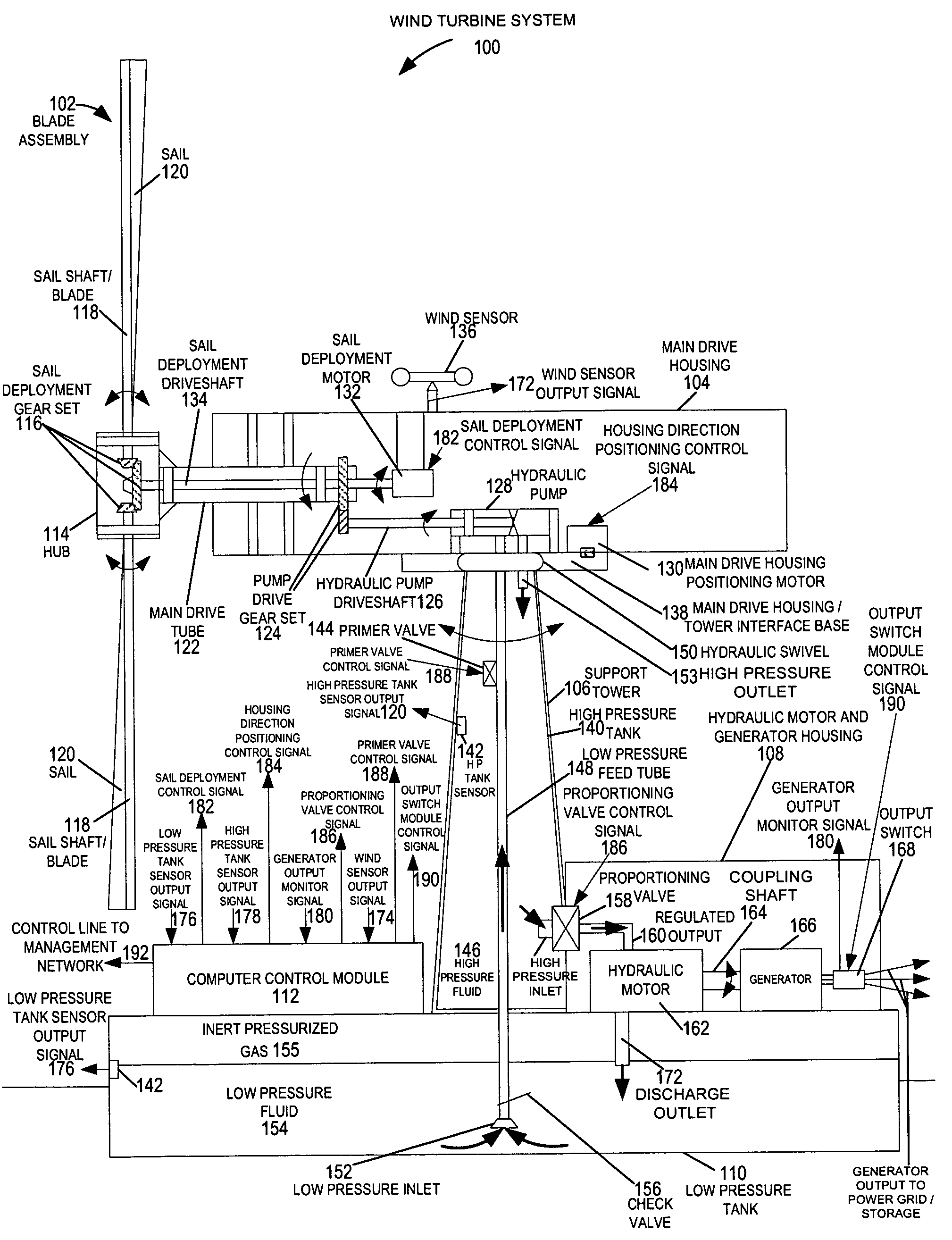
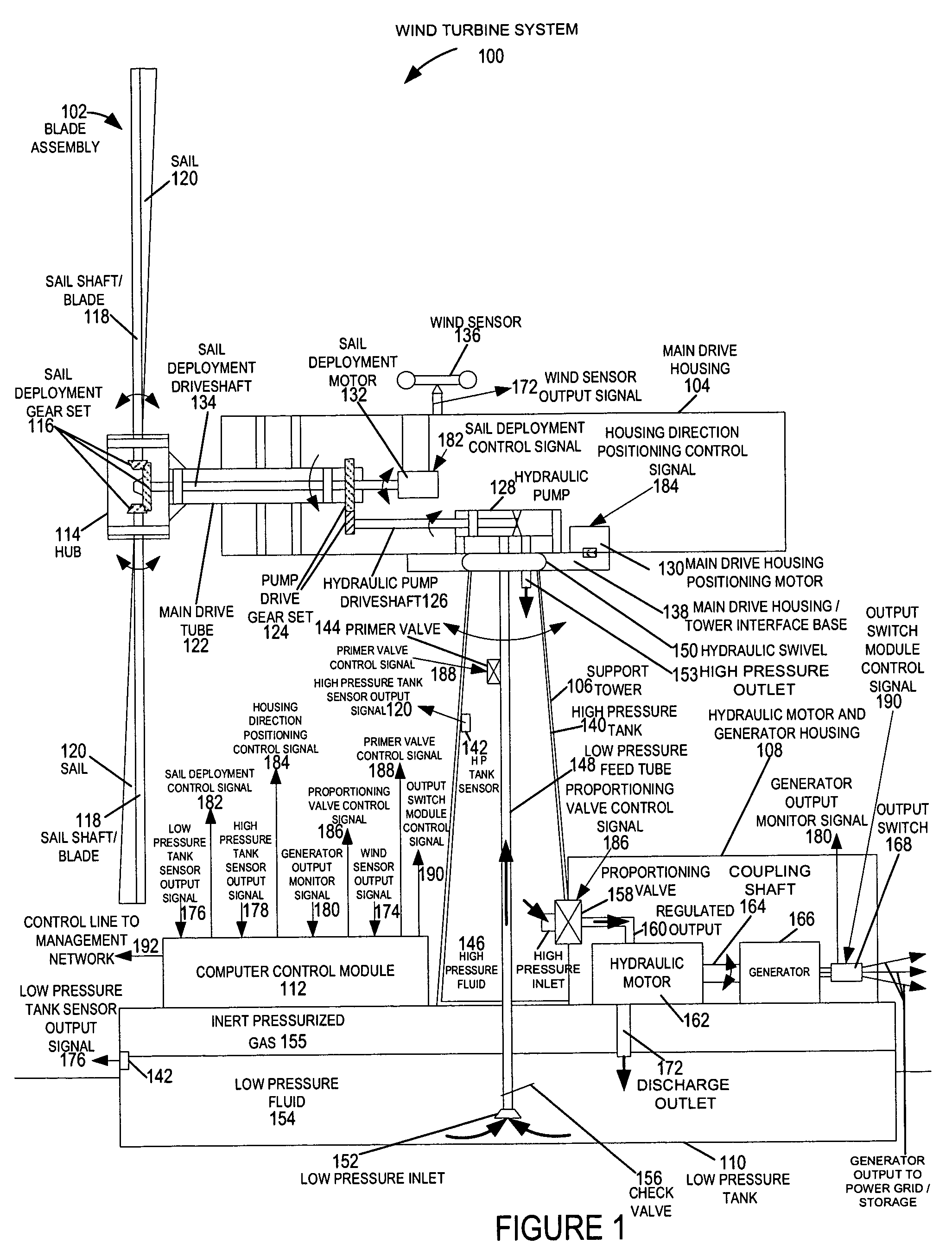
[0031]FIG. 1 is a drawing of an exemplary wind turbine system 100 implemented in accordance with the present invention and using methods of the present invention. Exemplary wind turbine system 100 includes a blade assembly 102, a main drive housing 104, a support tower 106, a hydraulic motor and generator housing 108, a low pressure tank 110, and a computer control module 112.

[0032]The blade assembly 102 includes a hub 114, a sail deployment gear set 116, a plurality of sail shafts / blades 118, and a plurality of retractable sails 120. The blade assembly 102 is used to capture wind energy. The blade assembly 102, in some embodiments includes a rolling reefing sail system, whereby the area of the sails is variably adjustable. The sail shaft / blades 118, e.g., carbon fiber masts, coupled to hub 114 are attached to the sail deployment gear set 116, and can be rotated to let out or retract the sails 120 which are attached to the sail shaft / blades 118. In some embodiments, sensors are empl...


PUM


Abstract

A wind turbine system includes a variable blade assembly including adjustable sails and wing shaped masts expanding the wind velocity capture envelope. The blade assembly turns a hydraulic pump, which pressurizes fluid and stores the pressurized fluid in a chamber in the support tower. Pressurized fluid is directed via an electronically controllable proportioning valve to a hydraulic motor which is coupled to an electric generator. A computer control module operates the proportioning valve regulating pressure to the hydraulic motor, maintaining generator rotational speed, and providing consistent output frequency to the power grid. Stored energy in the high pressure tank is used to continue generator operation after the winds cease, allowing early warning notification to the power management system of impending power loss. Residual pressure maintained in the high pressure tank allows restart operations via hydraulic pressure rather than power grid energy drain. On site high energy capacitors store additional energy.

Description

FIELD OF THE INVENTION[0001]The present invention relates to alternative energy sources, and more particularly, to methods and apparatus for advanced wind turbine design.BACKGROUND[0002]Current wind turbine designs typically utilize direct drive generators or gear driven generators coupled to the wind turbine shaft. In such designs, there is an inherent problem in that as the wind speed varies the output frequency of the generator will also vary. However, for the generator output to be usable by the power grid, the output signal needs to be converted to match the power grid frequency, which is 60 Hz in the United States and 50 Hz in Europe. Typically, an additional frequency conversion stage is used to convert from the variable wind turbine generator output frequency to the constant grid frequency. Such an additional frequency conversion stage can include invertors and / or other phase correction circuitry. Such conversion stages can be costly and complex to implement and maintain. In...

Claims


Application Information

Patent Timeline
Patent Type & Authority Patents(United States)
IPC IPC(8): F03B9/00H02P9/04
CPCF03D7/0236F03D9/001F03D9/021F03D9/028Y02E60/17F05B2260/406Y02E10/721Y02E60/15Y02E10/723F05B2240/3121F03D9/11F03D9/17F03D9/25F03D9/28F03D13/20F03D15/10F03D17/00F03D80/80Y02E10/72Y02E10/728Y02E60/16Y02E70/30Y02P80/10Y02P90/50
Inventor MCCLINTIC, FRANK
Owner MCCLINTIC FRANK
Why Eureka
Try Eureka