Method and apparatus for generating an inert gas on a vehicle

a technology of inert gas and vehicle, which is applied in the field of vehicle compartments, can solve the problems of difficult to quickly prepare the aircraft for flight, insufficient flow rate of obiggs, and gradual consumption of stored nea

Active Publication Date: 2005-11-10
THE BOEING CO
View PDF7 Cites 101 Cited by
  • Summary
  • Abstract
  • Description
  • Claims
  • Application Information

AI Technical Summary

Benefits of technology

[0007] In another aspect, a method of generating inert gas on a vehicle is provided for supplying the inert gas to a fuel tank. The method includes supplying a flow of gas having a nitrogen component and an oxygen component to a gas separating module, separating the flow of gas into a nitrogen-enriched gas flow and an oxygen-enriched gas flow using the gas separating module, wherein the nitrogen-enriched gas flow has an oxygen concentration low enough that the nitrogen-enriched gas flow is generally inert, and delivering the nitrogen-enriched gas flow from the gas separating module to the fuel tank at a multiplicity of unique flow rates, wherein each unique flow rate of the multiplicity of unique flow rates corresponds to a different operating condition of the aircraft.
[0008] In another aspect, a method of generating inert gas on a vehicle is provided for supplying the inert gas to a fuel tank having a fuel tank vent. The method includes supplying a flow of gas having a nitrogen component and an oxygen component to a gas separating module, separating the flow of gas into a nitrogen-enriched gas flow and an oxygen-enriched gas flow using the gas separating module, wherein the nitrogen-enriched gas flow has an oxygen concentration low enough that the nitrogen-enriched gas flow is generally inert, delivering nitrogen-enriched gas from the nitrogen-enriched gas flow to the fuel tank without delivering the nitrogen-enriched gas through the fuel tank vent, and delivering nitrogen-enriched gas from the nitrogen-enriched gas flow to the fuel tank vent.
[0009] In another aspect, a method of generating inert gas on a vehicle is provided for supplying the inert gas to a fuel tank. The method includes supplying a flow of gas having a nitrogen component and an oxygen component to a gas separating module, separating the flow of gas into a nitrogen-enriched gas flow and an oxygen-enriched gas flow using the gas separating module, wherein the nitrogen-enriched gas flow has an oxygen concentration low enough that the nitrogen-enriched gas flow is generally inert, and delivering the nitrogen-enriched gas flow from the gas separating module to the fuel tank at a plurality of unique flow rates, wherein the flow of gas supplied to the gas separating module has a unique temperature for each unique flow rate of the plurality of unique flow rates.
[0010] In even another aspect, the present invention includes an inert gas generating system for generating inert gas on a vehicle having a fuel tank. The system includes an inlet for receiving a flow of gas having a nitrogen component and an oxygen component from a gas source, a heat exchanger downstream from the inlet and in fluid communication with the inlet for cooling gas received from the inlet, and a gas separation module downstream from the heat exchanger and in fluid communication with the heat exchanger for separating gas received from the heat exchanger into a nitrogen-enriched gas flow and an oxygen-enriched gas flow. The gas separation module is adapted to generate a flow rate of the nitrogen-enriched gas flow of about 40 pounds per minute with an oxygen content less than or equal to about 9.8 percent by volume.

Problems solved by technology

However, some OBIGGS may not generate the NEA at a flow rate sufficient to ensure the gas above the fuel in the tank is incombustible during some operating conditions of the aircraft.
Because the OBIGGS may not generate the NEA fast enough to fully charge the system during short flights, flight crews may be required to project usage of NEA and charge the storage tanks accordingly before flight.
Additionally, the stored NEA is gradually consumed as the ullage temperature changes while the aircraft is parked.
If the aircraft (and therefore the OBIGGS) is not operated daily, it may take several hours to supply the fuel tanks with sufficient NEA, making it difficult to quickly prepare the aircraft for flight.
The storage compressors and tanks may need to be replaced periodically and can be difficult to remove due to their location, size, and weight.
Furthermore, potential leakage from the storage tanks and associated components may require maintenance personal to sample an oxygen level adjacent the OBIGGS before accessing the OBIGGS for maintenance.
Even small leaks from the storage tanks and associated components may prevent the storage tanks from storing enough NEA to sufficiently supply the fuel tank so the gas above the fuel is incombustible during descent of the aircraft.

Method used


Image

  • Method and apparatus for generating an inert gas on a vehicle
  • Method and apparatus for generating an inert gas on a vehicle
  • Method and apparatus for generating an inert gas on a vehicle

Examples


Embodiment Construction

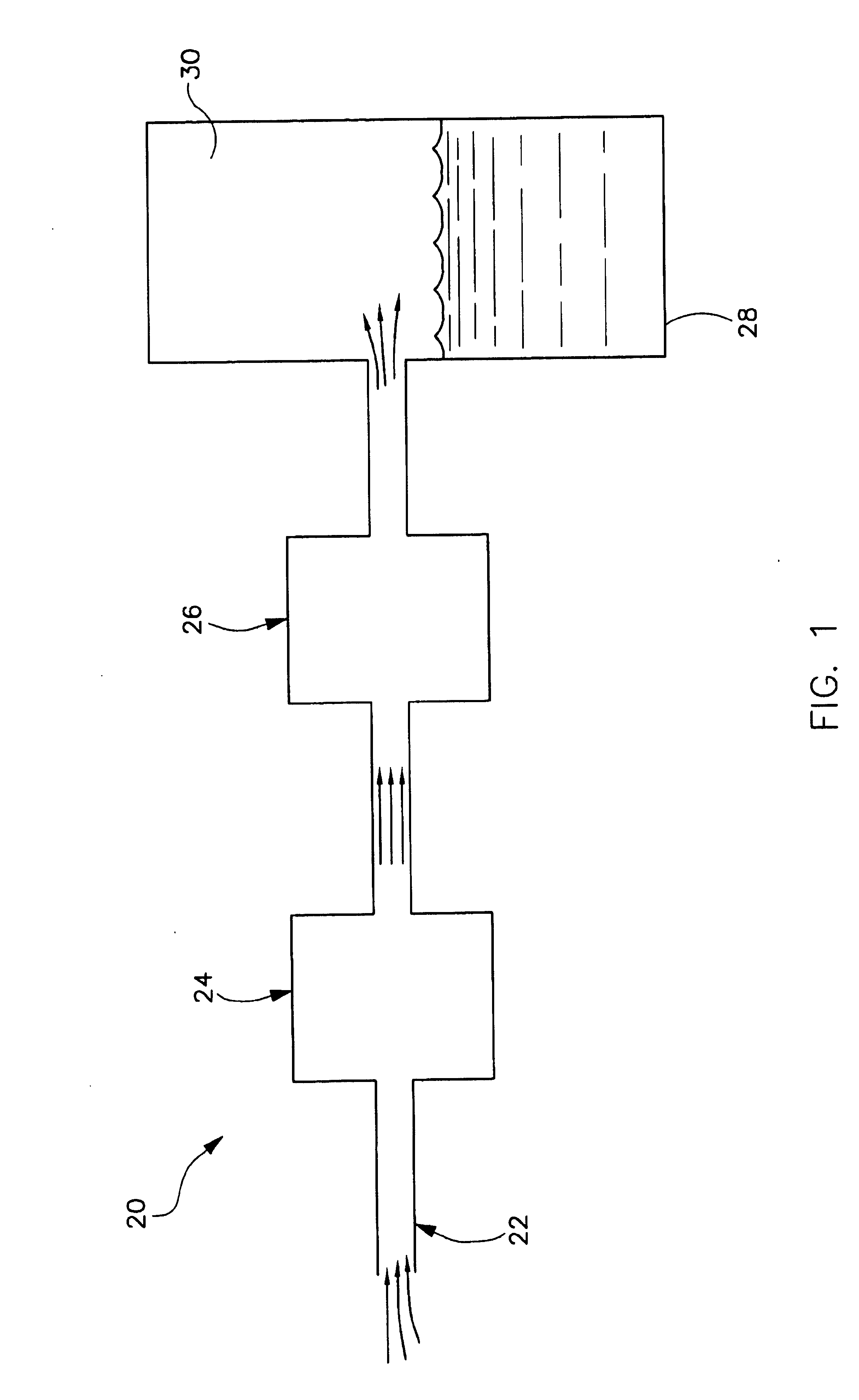
[0017] Referring now to the drawings, and more specifically to FIG. 1, an inert gas generating system of the present invention is designated in its entirety by the reference numeral 20. The system 20 includes an inlet (generally designated by 22 ), a heat exchanger (generally designated by 24) downstream from and in fluid communication with the inlet, and a gas separation module (generally designated by 26) downstream from and in fluid communication with the heat exchanger. Generally, the inlet 22 receives a flow of gas from a gas source (not shown), the heat exchanger 24 cools gas received from the inlet 22, and the gas separation module 26 generates a generally inert gas flow from gas received from the heat exchanger. The system 20 supplies the inert gas flow to a fuel tank 28 of a vehicle (not shown) to ensure the gas above the fuel in the fuel tank is generally incombustible. More specifically, the system 20 supplies the inert gas flow to an ullage 30 of the fuel tank 28 to fill...


PUM

PropertyMeasurementUnit
pressureaaaaaaaaaa
flow rateaaaaaaaaaa
pressureaaaaaaaaaa

Abstract

An inert gas generating system for generating inert gas on a vehicle having a fuel tank and a fuel tank vent. The system includes an inlet for receiving a flow of gas having a nitrogen component and an oxygen component from a gas source, a heat exchanger downstream from the inlet and in fluid communication with the inlet for cooling gas received from the inlet, and a gas separation module downstream from the heat exchanger and in fluid communication with the heat exchanger for separating gas received from the heat exchanger into a nitrogen-enriched gas flow and an oxygen-enriched gas flow. The gas separation module is adapted to deliver nitrogen-enriched gas from the nitrogen-enriched gas flow to the fuel tank without delivering the nitrogen-enriched gas through the fuel tank vent. The gas separation module is also adapted to deliver nitrogen-enriched gas from the nitrogen-enriched gas flow to the fuel tank vent.

Description

[0001] This invention was made with Government support under contract number F33657-96-C-2059, awarded by the U.S. Air Force. The government has certain rights in this invention.BACKGROUND OF THE INVENTION [0002] The present invention relates generally to vehicle compartments, and more specifically to supplying vehicle compartments (e.g., a fuel tank) with an inert gas to prevent the compartments from combusting. [0003] It is well known to supply an inert gas, such as nitrogen-enriched air (NEA), to the ullages (i.e., the portion of a tank above the liquid) of an aircraft fuel tank to prevent the tank from combusting. In the past, storage tanks on the aircraft have been charged with compressed NEA from an external source to supply the fuel tanks during flight. Currently, some aircraft include on-board inert gas generating systems (OBIGGS) for generating the NEA on-board the aircraft from conditioned engine bleed air. However, some OBIGGS may not generate the NEA at a flow rate suffi...

Claims


Application Information

Patent Timeline
Patent Type & Authority Applications(United States)
IPC IPC(8): A62B7/14A62C3/06A62C3/08A62C99/00B01D53/02B64D37/32
CPCA62B7/14A62C3/06Y02T50/44B01D2257/104B64D37/32A62C3/08Y02T50/40
Inventor SNOW, DONALD R. JR.
Owner THE BOEING CO
Why Eureka
Try Eureka