
Methods and systems for an intake oxygen sensor

a technology of gas constituent sensor and sensor, which is applied in the direction of mechanical equipment, machines/engines, electric control, etc., can solve the problems of sensor not providing an accurate estimate of how much excess fuel is in the egr, fuel system error, and incorrect adjustment of spark timing, throttle position, etc., to reduce regulated emissions and improve fuel economy.

Active Publication Date: 2015-04-16
FORD GLOBAL TECH LLC
View PDF46 Cites 35 Cited by
  • Summary
  • Abstract
  • Description
  • Claims
  • Application Information

AI Technical Summary

Benefits of technology

The patent text describes a method for improving the accuracy of estimating the amount of exhaust gas recirculation (EGR) in an engine system. This is important for controlling emissions and fuel economy. The method involves using an intake gas constituent sensor, such as an oxygen sensor, to measure the EGR based on a change in oxygen concentration. However, the sensor can be affected by the air-fuel ratio of the EGR. To account for this, the method corrects the sensor output based on the richness of the EGR air-fuel ratio to compensate for variations in the sensor output. This allows for a more accurate estimation of the EGR and improves fuel control. The method also inferred the amount of excess fuel in the EGR and adjusted engine fuel injection accordingly, reducing fuel system errors and improving engine performance. Overall, this method improves the accuracy of EGR dilution estimation and fuel control in the engine system.

Problems solved by technology

However, the inventors have identified potential issues with such an approach.
As a result, any adjustments to spark timing, throttle position, and / or fuel injection that are based on the adjusted calibration coefficient may be incorrect.
As another example, in the presence of rich EGR, the sensor does not provide an accurate estimate of how much excess fuel is in the EGR.
In the closed-loop fuel control, the adaptive fuel may adapt for the excess fuel in the EGR but the adaptive correction will be attributed to a fuel system error.
This may falsely trigger a fuel system error if the correction is above a threshold.
The problem may be exacerbated due to a delay between the timing of fuel injection and the sensing of the fuel at the intake oxygen sensor.
Likewise, there may be delay between the EGR estimated at an exhaust oxygen sensor relative to the EGR estimated at the intake oxygen sensor.
In either case, engine fueling and EGR control may be disrupted.

Method used


Image

  • Methods and systems for an intake oxygen sensor
  • Methods and systems for an intake oxygen sensor
  • Methods and systems for an intake oxygen sensor

Examples


Embodiment Construction

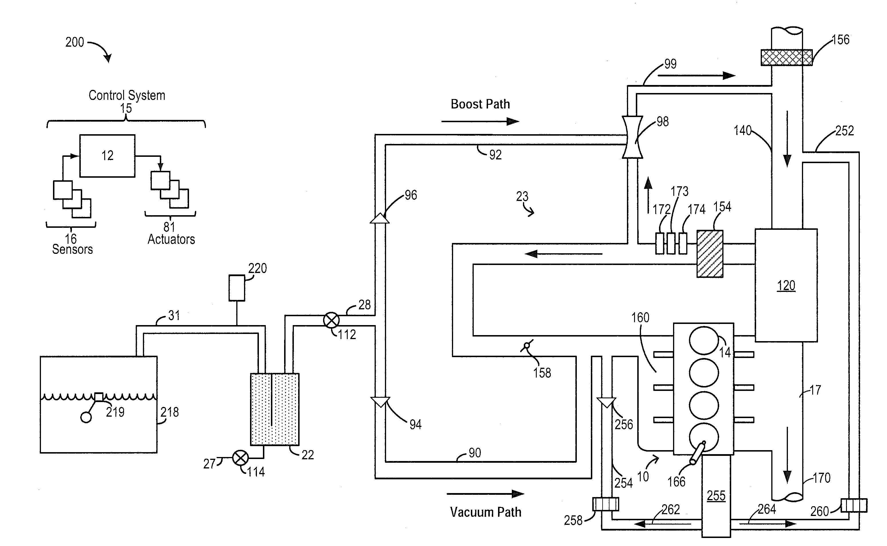
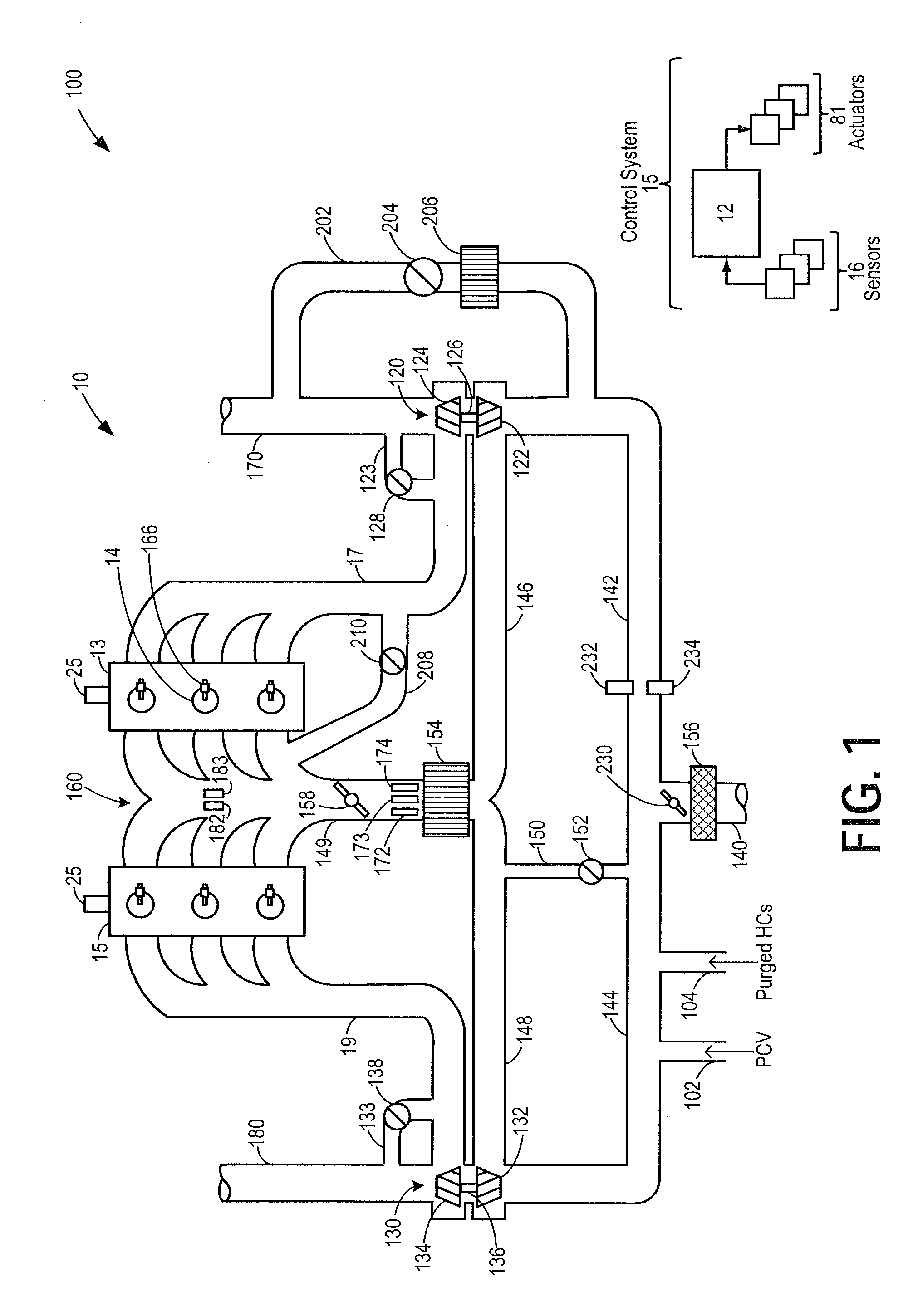
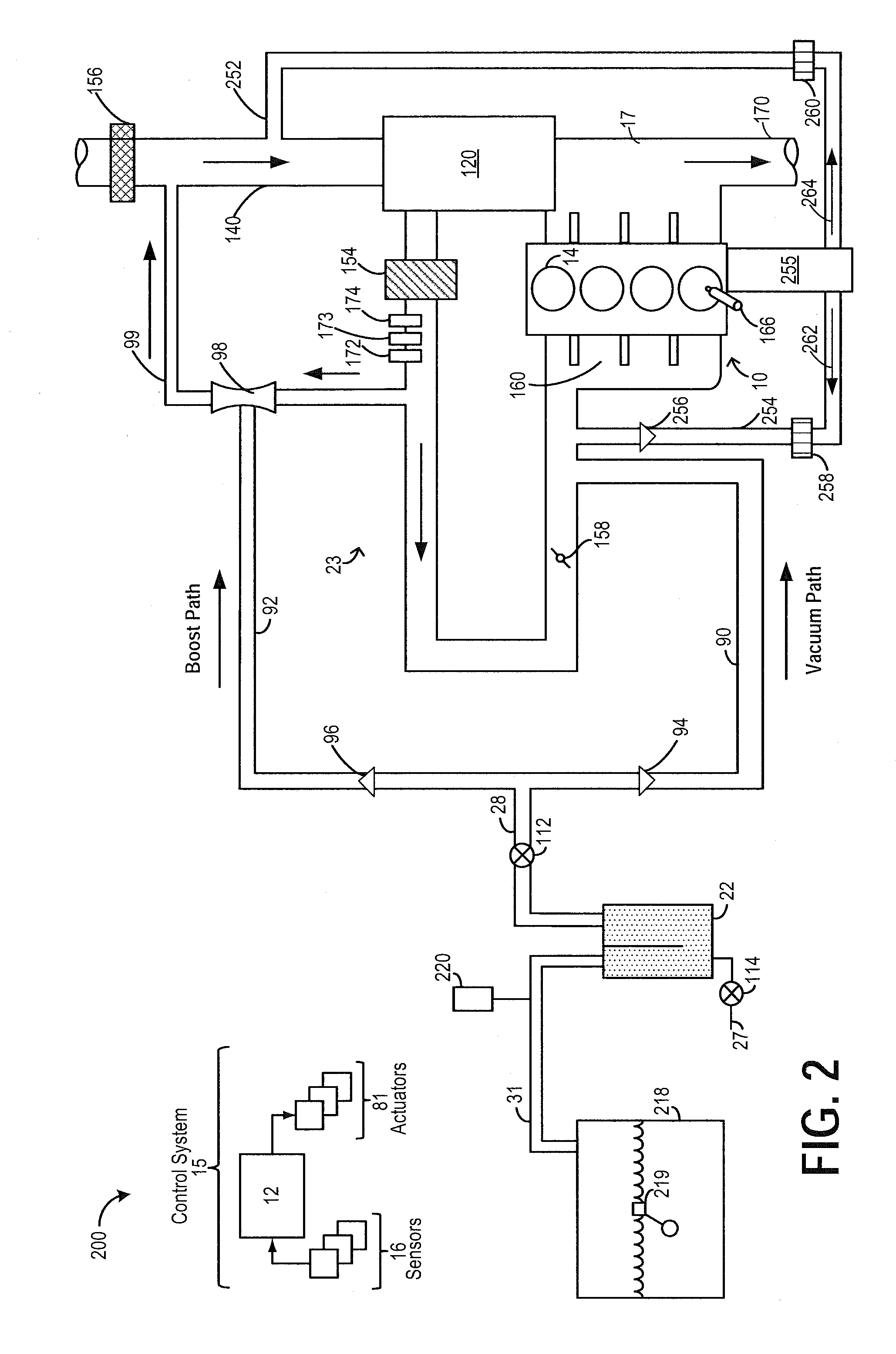
[0014]The present description is related to methods and system for using an intake manifold sensor for sensing an amount of EGR flow to an engine system, such as the engine systems of FIGS. 1-2. To overcome the effect of rich or lean EGR, as determined by an exhaust gas oxygen sensor, on an output of an intake gas oxygen sensor, as shown at FIGS. 3A-C, an inferred EGR estimate may be adjusted with a correction factor. A controller may be configured to perform a control routine, such as the routine of FIG. 4 to learn an amount of excess fuel in rich EGR, or excess oxygen in lean EGR, ingested into the engine and adjust an EGR flow accordingly. An output of the sensor, as well as an EGR dilution estimated by the sensor, may be adjusted to compensate for the effect of varying EGR air-fuel ratio on the output of the sensor. In this way, accuracy of EGR estimation by an intake oxygen sensor is increased.

[0015]FIG. 1 shows a schematic depiction of an example turbocharged engine system 100...


PUM


Abstract

Methods and systems are provided for correcting an EGR rate determined based on an intake manifold oxygen sensor based on an air-fuel ratio of EGR. The output of the sensor is corrected to compensate for extra fuel in rich EGR or extra air in lean EGR and used to reliably estimate the EGR rate. One or more engine operating parameters are adjusted based on an uncorrected output of the sensor.

Description

TECHNICAL FIELD[0001]The present application relates generally to a gas constituent sensor included in an intake system of an internal combustion engine.BACKGROUND AND SUMMARY[0002]Engine systems may utilize recirculation of exhaust gas from an engine exhaust system to an engine intake system (intake passage), a process referred to as exhaust gas recirculation (EGR), to reduce regulated emissions and improve fuel economy. An EGR system may include various sensors to measure and / or control the EGR. As one example, the EGR system may include an intake gas constituent sensor, such as an oxygen sensor, which may be employed during non-EGR conditions to determine the oxygen content of fresh intake air. During EGR conditions, the sensor may be used to infer EGR based on a change in oxygen concentration due to addition of EGR as a diluent. One example of such an intake oxygen sensor is shown by Matsubara et al. in U.S. Pat. No. 6,742,379. The EGR system may additionally or optionally inclu...

Claims


Application Information

Patent Timeline
Patent Type & Authority Applications(United States)
IPC IPC(8): F02D43/00
CPCF02D43/00F02D41/0072F02D41/1401F02D41/144F02D41/1441F02D41/1456F02D41/30F02D41/005F02D2041/141F02D2041/1431Y02T10/40
Inventor SURNILLA, GOPICHANDRACLARK, TIMOTHY JOSEPHHILDITCH, JAMES ALFREDGERHART, MATTHEW JOHN
Owner FORD GLOBAL TECH LLC
Learn More