Vitreoretinal instrument

a technology of retinal instruments and instruments, applied in the field of retinal surgery, can solve the problems of loss of vision, further complicating retinal reattachment, and obscuring the visual field

Active Publication Date: 2007-10-23
ALCON INC
View PDF19 Cites 49 Cited by
  • Summary
  • Abstract
  • Description
  • Claims
  • Application Information

AI Technical Summary

Problems solved by technology

Both of these conditions result in a loss of vision.
Further, these instruments sometimes cause mechanical damage to the chori

Method used


Image

  • Vitreoretinal instrument
  • Vitreoretinal instrument
  • Vitreoretinal instrument

Examples


Embodiment Construction

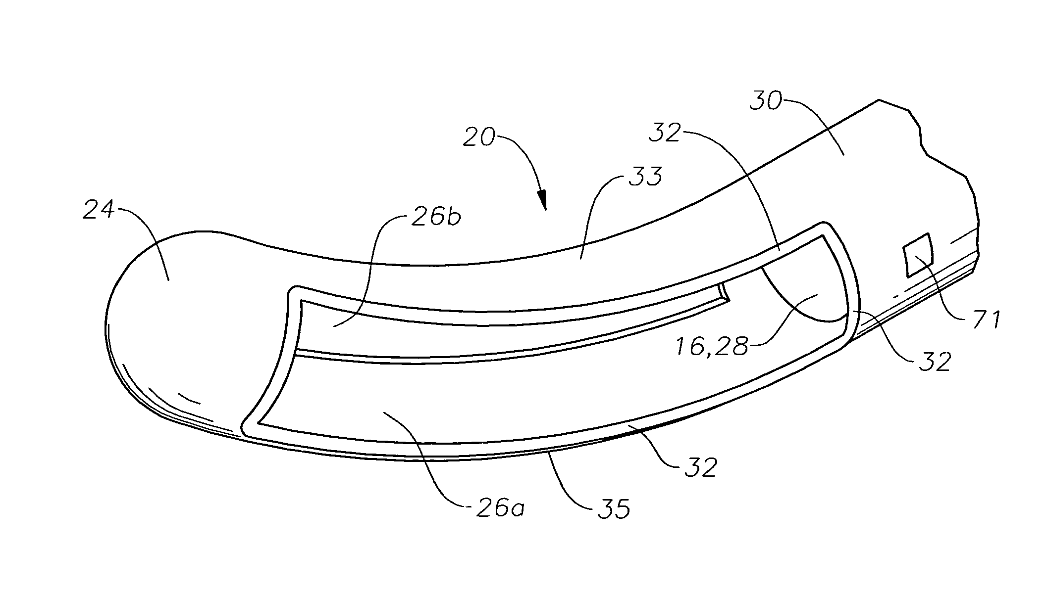
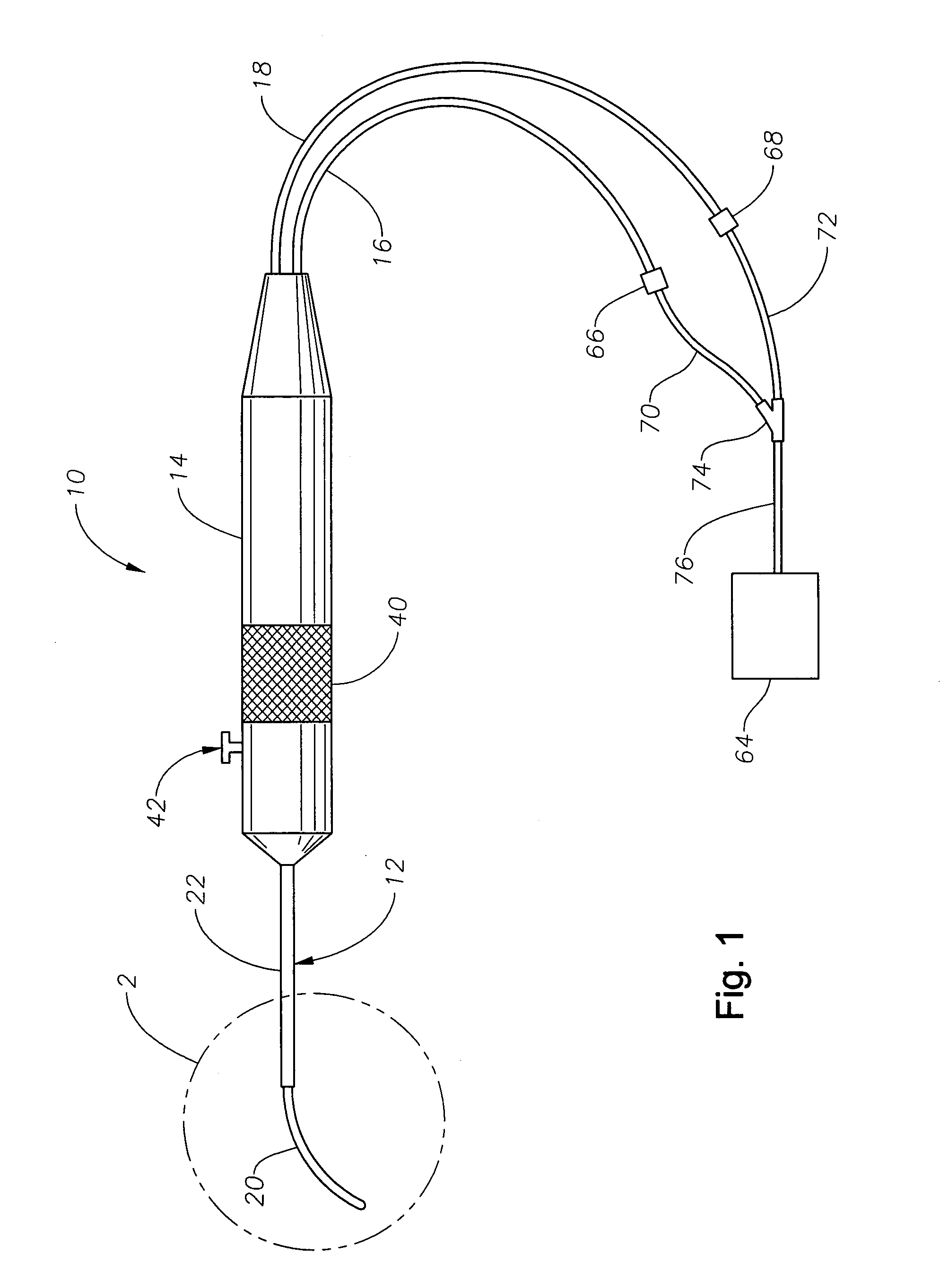
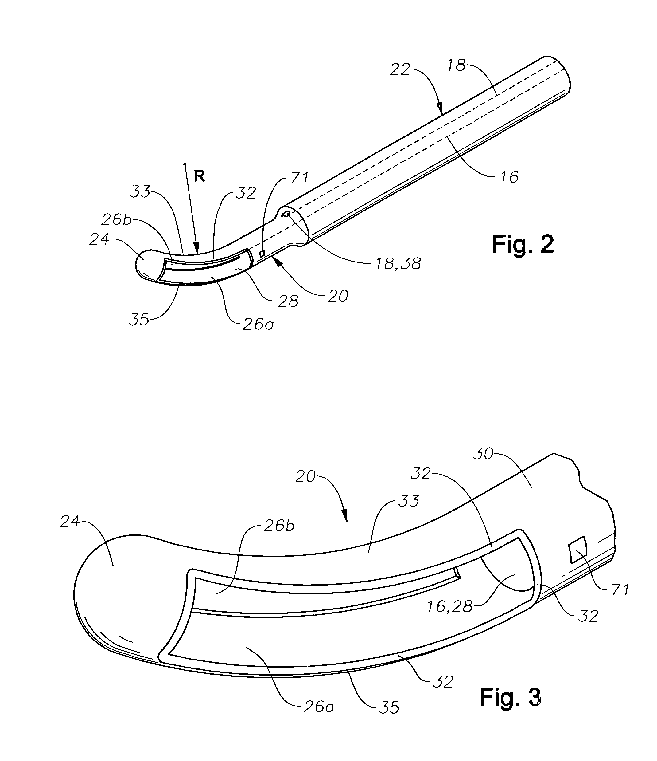
[0016]The preferred embodiments of the present invention and their advantages are best understood by referring to FIGS. 1 through 4 of the drawings, like numerals being used for like and corresponding parts of the various drawings.

[0017]Instrument 10 generally includes a cannula 12 on its distal end, a handle 14, and flexible tubing 16 and 18 extending from its proximal end. Cannula 12 preferably includes a curved, distal portion 20 and a straight, proximal portion 22. Curved portion 20 preferably has a radius of curvature R substantially equal to the radius of curvature of the human eye. Curved portion 20 also preferably has a closed tip 24 having a smooth, convex surface for interfacing with the retina. Alternatively, closed tip 24 may have a sharpened, needle-like tip. Curved portion 20 also has dual side ports 26a and 26b that open to a lumen 28 of cannula 12. Side ports 26a and 26b are preferably fluidly coupled and are disposed at an angle of about 90 degrees from the plane of...


PUM


Abstract

An improved instrument for removing subretinal fluid and performing fluid exchanges in vitreoretinal surgery is disclosed. The instrument includes a cannula with a curved distal portion and a side port on the curved distal portion for aspirating subretinal fluid. The instrument also includes a second port for aspirating a second fluid from the vitreous cavity during a fluid exchange.

Description

[0001]This application claims the priority of U.S. Provisional Application No. 60 / 419,123 filed Oct. 17, 2002.FIELD OF THE INVENTION[0002]The present invention generally pertains to vitreoretinal surgery and more particularly to improved instruments suitable for subretinal fluid removal and fluid exchanges typically used in such surgeries.DESCRIPTION OF THE RELATED ART[0003]In a healthy human eye, the retina is physically attached to the choroid in a generally circumferential manner behind the pars plana. The vitreous humor, a transparent jelly-like material that fills the posterior segment of the eye, helps to cause the remainder of the retina to lie against, but not physically attach, to the choroid.[0004]Sometimes a portion of the retina becomes detached from the choroid. Other times a portion of the retina may tear, allowing vitreous humor, and sometimes aqueous humor, to flow between the retina and the choroid, creating a build up of subretinal fluid. Both of these conditions r...

Claims


Application Information

Patent Timeline
IPC IPC(8): A61M1/00
CPCA61M1/0045A61M1/0064A61F9/00736A61M1/7415A61M1/774A61M1/772
Inventor CHARLES, STEVEN T.
Owner ALCON INC
Why Eureka
Try Eureka