Method and apparatus for driving plasma display panel

a plasma display panel and plasma technology, applied in the direction of instruments, static indicating devices, etc., can solve the problems of increasing the voltage of the sustain pulse sus, i, sustain voltage vs, and applying from the outside during the sustain period, so as to prevent undesired discharges.

Inactive Publication Date: 2007-10-23
LG ELECTRONICS INC
View PDF26 Cites 21 Cited by
  • Summary
  • Abstract
  • Description
  • Claims
  • Application Information

AI Technical Summary

Benefits of technology

[0018]Accordingly, it is an object of the present invention to provide a method and apparatus for driving a plasma display panel that can be driven at a low voltage and which prevent undesired discharge under a high temperature environment.
[0019]It is another object of the present invention to provide a method and apparatus for driving a plasma display panel that is adaptive for stabilizing address operation and sustain operation.

Problems solved by technology

Further, in the related art PDP, increase in the voltage of the sustain pulse SUS, i.e., the sustain voltage Vs, applied from the outside during the sustain period also cannot be avoided because of the small amount of wall charges accumulated on the sustain electrode Z upon the discharge during the set-down period SD.
Furthermore, the related art PDP has a problem in that undesired discharges frequently occur upon the address discharge because the wall charges within the cells are decreased and their operational conditions are changed in the high temperature environment.
Further, the related art PDP has a problem in that the address operation and the sustain operation is unstable because the undesired discharge may be generated in accordance with the initial state of the off cell upon the address discharge or the sustain discharge.

Method used


Image

  • Method and apparatus for driving plasma display panel
  • Method and apparatus for driving plasma display panel
  • Method and apparatus for driving plasma display panel

Examples


first embodiment

[0151]FIGS. 5 and 6 are waveform diagrams explaining a method for driving a PDP according to the present invention. FIG. 7 illustrates a change of wall charge distribution with the lapse of time within an on-cell in the event of the application of the waveform diagram of FIG. 6. FIGS. 8A to 8D are simulation results particularly representing a change of wall charge distribution for an initialization period. In FIGS. 8A to 8D, the axis of ordinates represents the amount of charge (C), and the horizontal axis represents distance (μm).

[0152]Referring to FIGS. 5 to 8, in the driving method for the PDP according to the first embodiment of the present invention, one frame period is time-divided into a plurality of sub-fields to drive the PDP. Each sub-field includes an initialization period for which only rising ramp waveforms are applied to the scan electrodes Y and the sustain electrodes Z to initialize the cells of a full screen, an address period for which cells are selected, a pre-er...

fifth embodiment

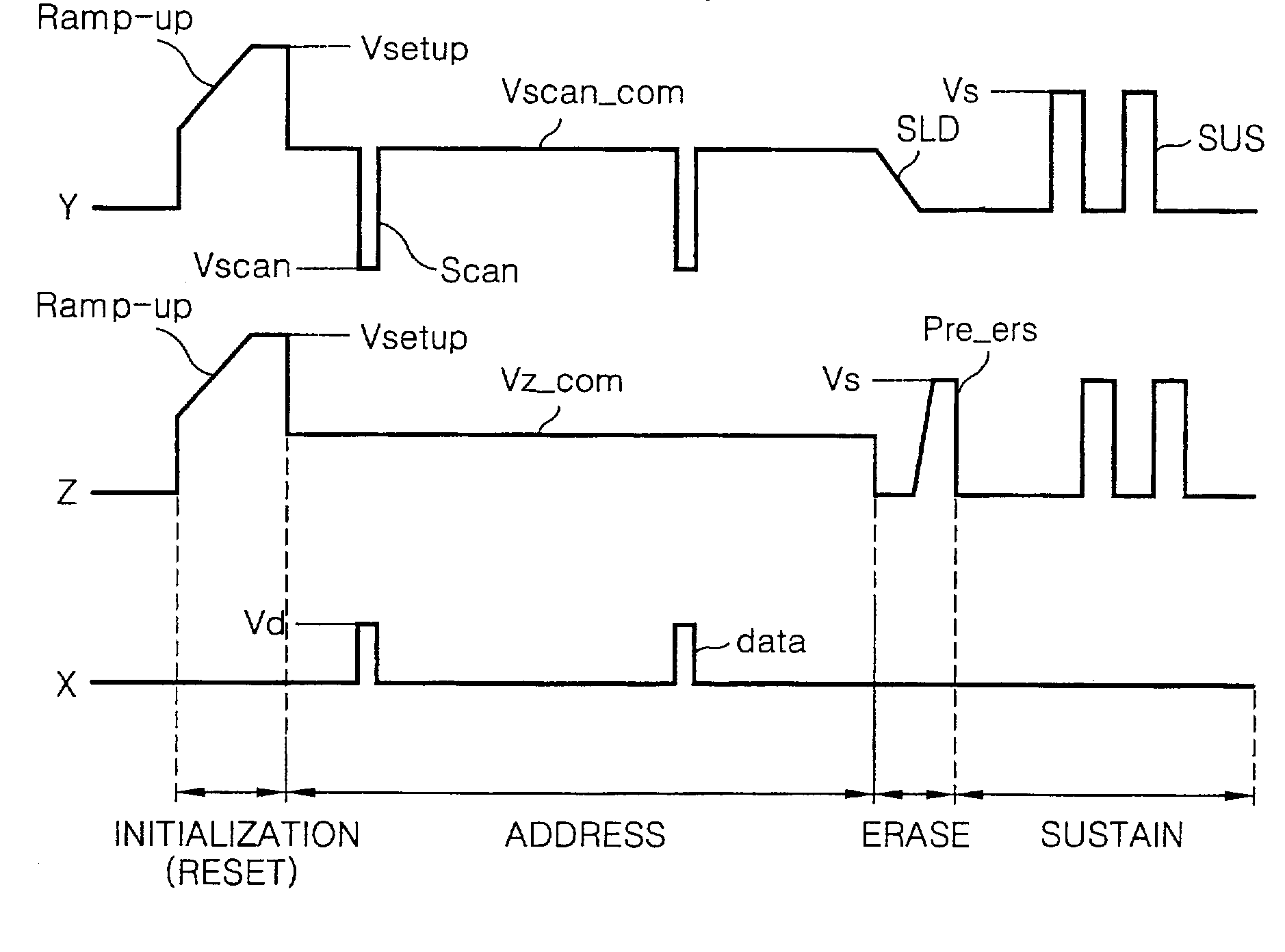
[0166]FIG. 14 is a waveform explaining a driving method for a PDP according to the present invention.

[0167]Referring to FIG. 14, in the driving method for the PDP according to this embodiment of the present invention, one frame period is time-divided into a plurality of sub-fields to drive the PDP, and the scan electrodes Y and the sustain electrodes Z are supplied with erase signals Pre-ers of a falling ramp waveform falling between the address period and the sustain period to eliminate the wall charges remaining within the off-cells.

[0168]In the initialization period (reset period), the cells of the full screen can be initialized by continuously applying the rising ramp waveforms and the falling ramp waveforms to the scan electrodes Y as in FIG. 3, or by applying only the rising ramp waveform to the scan electrodes Y and the sustain electrodes Z as in the present embodiment. Further details relating to this will be described later. Also, the initialization waveform can be applied ...

second embodiment

[0234]FIG. 34 is a waveform diagram representing waveforms, which are applied to a driving method for a PDP according to the twenty-second embodiment of the present invention.

[0235]Referring to FIG. 34, in the driving method for the PDP according to the present invention, after applying the rising ramp waveforms, Ramp-up, to the scan electrodes Y and the sustain electrodes Z in each sub-field, the falling ramp waveforms, Ramp-dn, are applied only to the scan electrodes Y to initialize the cells of the full screen.

[0236]In the initialization period (reset period), the rising ramp waveforms, Ramp-up, which rise substantially from the sustain voltage Vs to the setup voltage Vsetup at a designated slope, are simultaneously applied to the scan electrodes Y and the sustain electrodes Z. At the same time, the address electrodes X are supplied with 0V or the ground voltage GND. The rising ramp waveform, Ramp-up, simultaneously applied to the scan electrodes Y and the sustain electrodes Z li...


PUM


Abstract

The present invention relates to a method and apparatus for driving a plasma display panel that can be driven at a low voltage and prevent undesired discharge from being generated under high temperature environment.A method and apparatus for driving a plasma display panel according to an embodiment of the present invention includes a first step of applying an initialization signal to the first and second electrodes to initialize cells, the initialization signal has at least one rising part where a voltage rises and at least one sustain part where the voltage is sustained; a second step of applying a scan signal to any one of the first and second electrodes, and data to the third electrode to select the cell; and a third step of alternately applying sustain signals to the first and second electrodes to carry out a display for the selected cell.

Description

BACKGROUND OF THE INVENTION[0001]1. Field of the Invention[0002]The present invention relates to a plasma display panel PDP, and more particularly to a method and apparatus for driving a plasma display panel that can be driven at a low voltage and which prevents undesired discharge under a high temperature environment. Further, the present invention relates to a method and apparatus for driving a plasma display panel that is adaptive for stabilizing address operation and sustain operation.[0003]2. Description of the Related Art[0004]A plasma display panel displays a picture by using ultraviolet rays to cause phosphorus to emit light, with the ultraviolet rays being generated when producing discharge in an inert mixed gas such as He+Xe, Ne+Xe, He+Xe+Ne. Such a PDP is not only easily made into a thin film and a large-scale unit, but also has improved picture quality owing to recent technology development.[0005]Referring to FIG. 1, discharge cells of a three-electrode AC surface discha...

Claims


Application Information

Patent Timeline
Patent Type & Authority Patents(United States)
IPC IPC(8): G09G3/28G09G3/20G09G3/288G09G3/291G09G3/292G09G3/293G09G3/294G09G3/296G09G3/298
CPCG09G3/2022G09G3/2922G09G3/2927G09G3/293G09G3/2935G09G3/294G09G3/2932G09G2320/0228G09G2310/066
Inventor YOON, SANG JINPARK, EUNG CHULKANG, BONG KOOHAN, JUNG GWAN
Owner LG ELECTRONICS INC
Why Eureka
Try Eureka