Missile control system and method

a technology of missile control and missile engine, applied in the field of missile control system, can solve the problem of adding significant amounts of mass to the divert attitude control system

Active Publication Date: 2007-10-30
RAYTHEON CO
View PDF40 Cites 19 Cited by
  • Summary
  • Abstract
  • Description
  • Claims
  • Application Information

AI Technical Summary

Problems solved by technology

Such mechanisms add significant amounts of mass to divert attitude control systems.
In addition, the pintle and its corresponding actuation system are generally located internally, where they disadvantageously may be exposed to a high-pressure, high-temperature environment of combustion-product gasses used to produce the thrust.

Method used


Image

  • Missile control system and method
  • Missile control system and method
  • Missile control system and method

Examples


Embodiment Construction

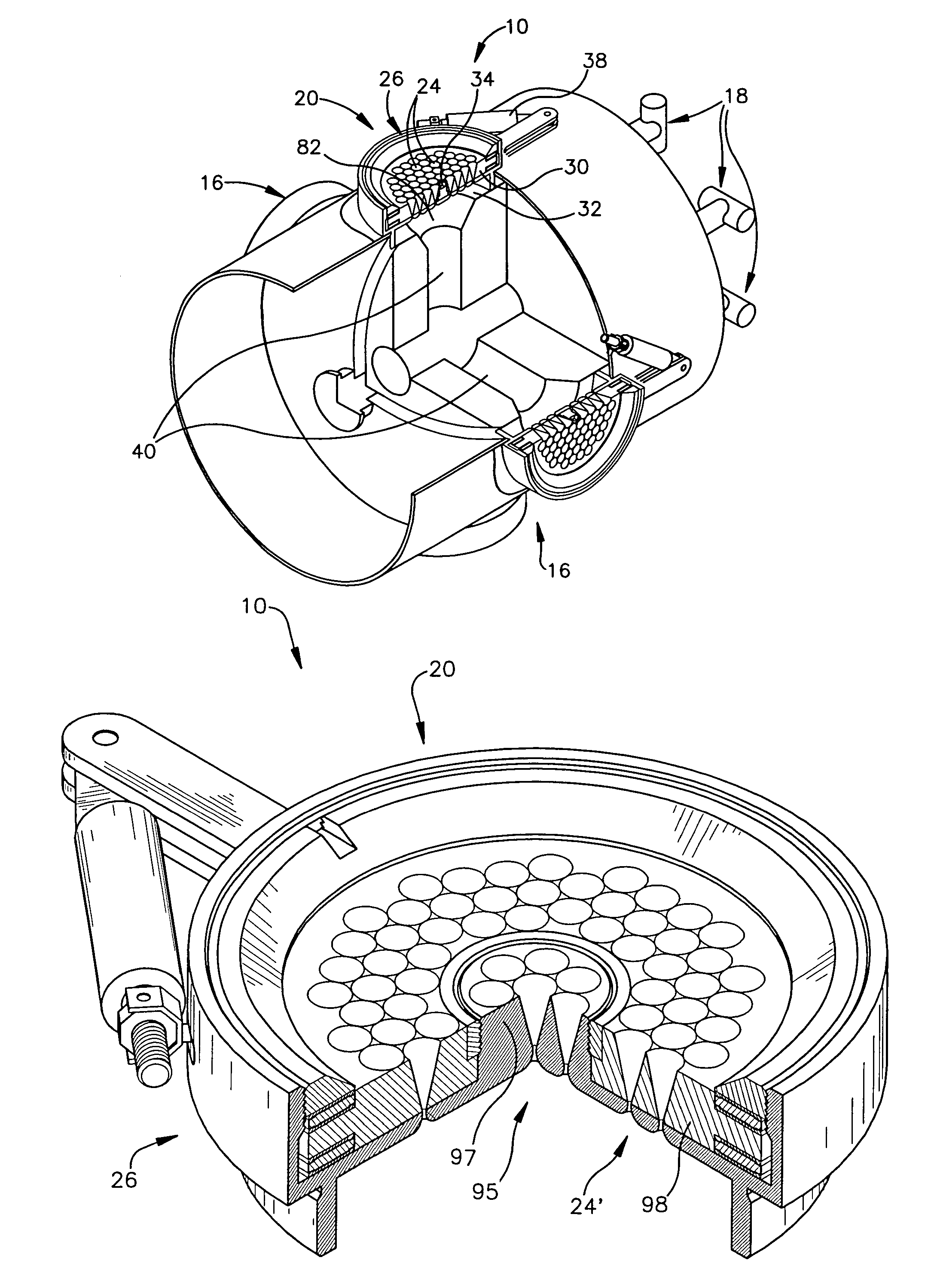
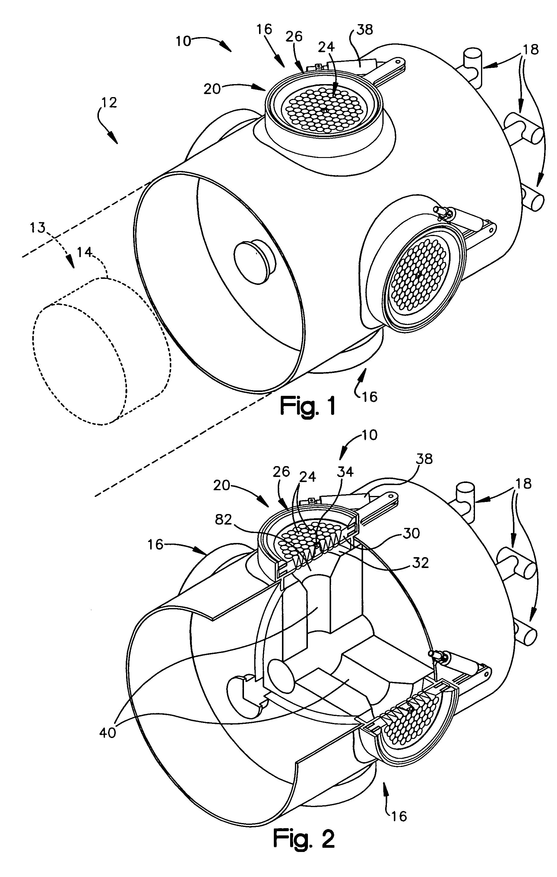
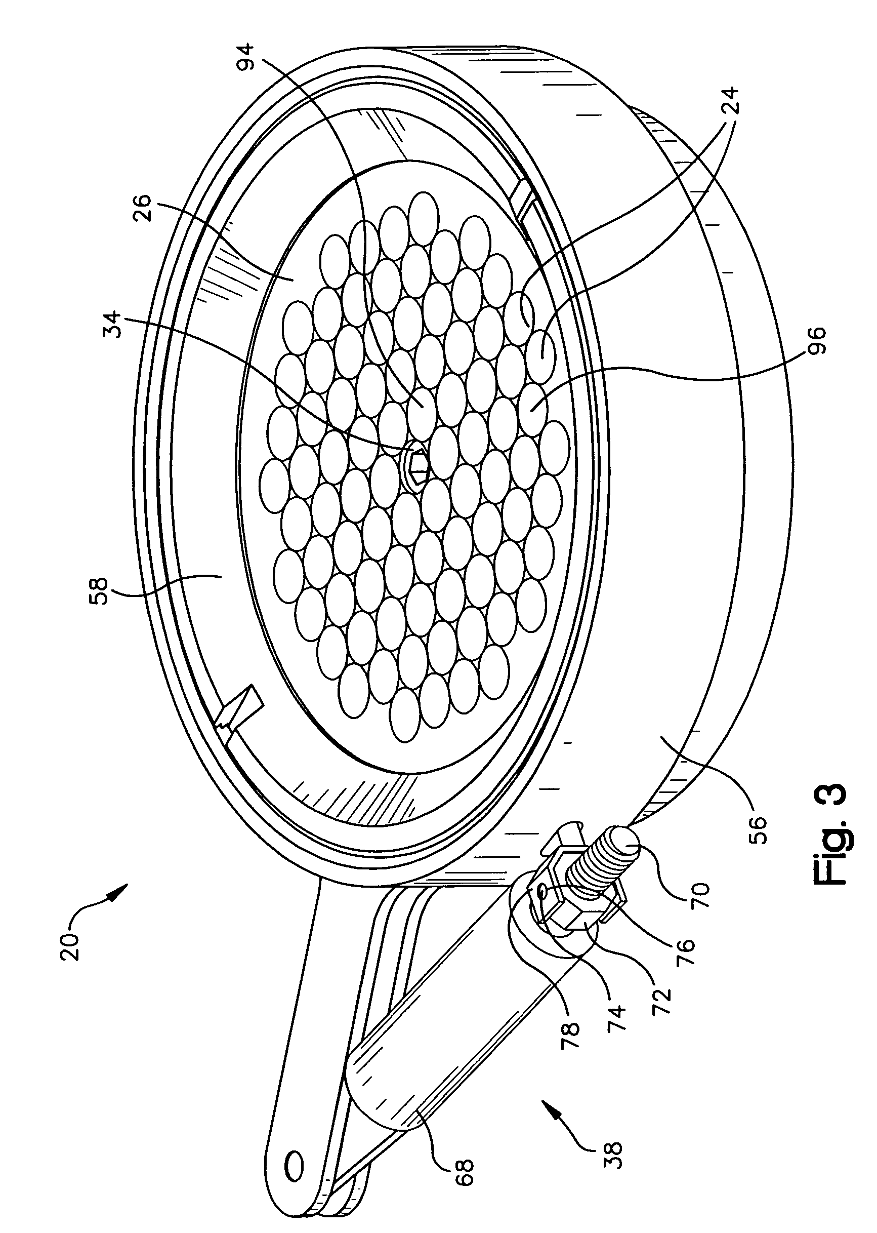
[0021]A missile includes a control system having divert and attitude control system thrusters with control valves. Each of the control valves has a nozzle plate having a plurality of small nozzles therein. The nozzle plate includes a pair of portions, one of which is rotatable relative to the other. Control of flow through the nozzle plate may be effected by relative positioning of the portions of the nozzle plate. An upstream convergent portion of the nozzle plate may be fixed relative to the missile, with a downstream throat and / or divergent portion of the nozzle plate moveable. Movement of the movable portion of the nozzle plate may be accomplished by use of an actuator that is external to the missile body. The control valve provides a simple, lightweight and compact way of controlling flow from a divert thruster.

[0022]FIGS. 1 and 2 show a control system 10 of a missile 12, for controlling thrust from a pressurized gas source 13, such as a solid fuel rocket engine 14. The control...


PUM


Abstract

A missile includes a control system having divert and attitude control system thrusters with control valves. Each of the control valves has a nozzle plate having a plurality of small nozzles therein. The nozzle plate includes a pair of portions, one of which is rotatable relative to the other. Control of flow through the nozzle plate may be effected by relative positioning of the portions of the nozzle plate. An upstream convergent portion of the nozzle plate may be fixed relative to the missile, with a downstream throat and / or divergent portion of the nozzle plate moveable. Movement of the movable portion of the nozzle plate may be accomplished by use of an actuator that is external to the missile body. The control valve provides a simple, lightweight and compact way of controlling flow from a divert thruster.

Description

BACKGROUND OF THE INVENTION[0001]1. Technical Field of the Invention[0002]The invention relates to missile systems, and in particular to control systems for missiles and rocket engines.[0003]2. Background of the Related Art[0004]Throttling control valves, such as used for divert thrusters for rockets and missiles, have typically involved a pintle that can be moved into and out of a convergent portion of a single convergent-divergent nozzle. Such mechanisms add significant amounts of mass to divert attitude control systems. In addition, the pintle and its corresponding actuation system are generally located internally, where they disadvantageously may be exposed to a high-pressure, high-temperature environment of combustion-product gasses used to produce the thrust.[0005]It will be appreciated from the foregoing that some improvements may be possible for throttling control valves for divert thrusters.SUMMARY OF THE INVENTION[0006]According to an aspect of the invention, a control val...

Claims


Application Information

Patent Timeline
Patent Type & Authority Patents(United States)
IPC IPC(8): B64C1/24
CPCF02K9/30F02K9/805F02K9/86F16K3/085F42B10/663F42B10/666F05D2250/324F05D2260/60F05D2250/323F05D2250/41F05D2240/128
Inventor CHASMAN, DANIEL B.LEAL, MICHAELHAIGHT, STEPHEN D.
Owner RAYTHEON CO
Why Eureka
Try Eureka