Color variations in a dimmable lighting device with stable color temperature light sources

a dimmable lighting and color temperature technology, applied in the field of electronic and lighting, can solve the problems of dramatic color temperature change, increase in intensity, and change in spectral power distribution

Active Publication Date: 2007-10-30
SIGNIFY HLDG BV
View PDF26 Cites 440 Cited by
  • Summary
  • Abstract
  • Description
  • Claims
  • Application Information

AI Technical Summary

Benefits of technology

[0020]In another embodiment of the present invention, a method of varying a color temperature of a lighting device includes receiving a dimmer signal on at least one of N input terminals, wherein the dimmer input signal indicates multiple dimming levels over time and N is a positive integer less than or equal to four (4) and receiving power from a voltage source on at least two of the N input terminals. The method further includes supplying a first drive current to a first light source, wherein the first light source has a stable first color temperature and supplying a second drive current to a second light source, wherein the second light source has a stable second color temperature. The method also includes varying the first and second drive currents in response to changes in the dimming levels, wherein varying the first and second drive currents varies a color temperature of the lighting device.

Problems solved by technology

Thus, increasing current supplied to an LED increases the intensity of the LED, and decreasing current supplied to the LED dims the LED.
Dimming an incandescent light source results in a dramatic change of spectral power distribution and, thus, results in a dramatic change in color temperature.
However, regardless of the mix of non-incandescent light sources in a lighting device, varying the dimming level to the lighting device changes the intensity of the light sources not the color temperature of the lighting device.

Method used


Image

  • Color variations in a dimmable lighting device with stable color temperature light sources
  • Color variations in a dimmable lighting device with stable color temperature light sources
  • Color variations in a dimmable lighting device with stable color temperature light sources

Examples


Embodiment Construction

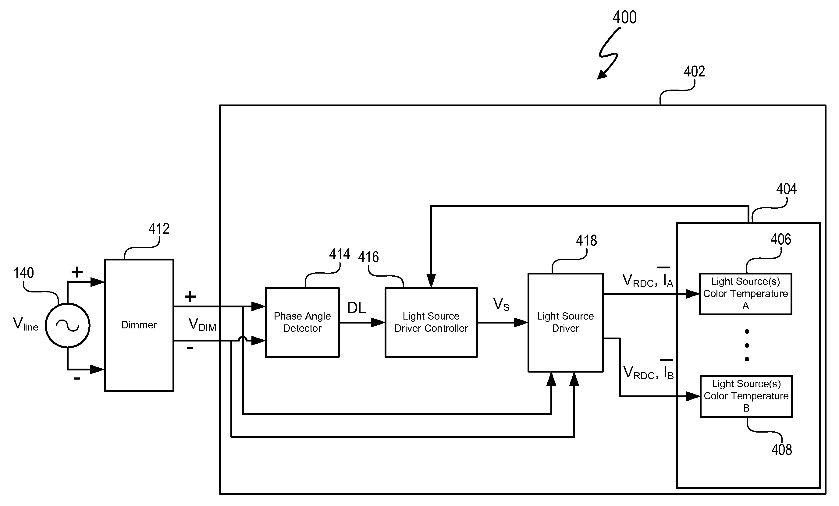
[0029]A method and system allow a lighting device having light sources with multiple color temperatures to vary a color temperature of the lighting device in response to changing dimming levels. The light sources are non-incandescent light sources, such as light emitting diodes and / or gas-discharge lights. A dimmer circuit provides a dimming signal that indicates a selected dimming level. The lighting device includes a light source driver and a light source driver controller that cooperate to vary drive currents to the light sources in response to the selected dimming level. By varying the drive currents in different relative amounts, the color temperature of the lighting device changes in response to dimming level changes. In at least one embodiment, changes in the color temperature of the lighting device in response to the dimming level changes simulates the color temperature changes of an incandescent light source. The components of the lighting device can be housed in a single h...


PUM


Abstract

A method and system allow a lighting device having light sources with multiple color temperatures to vary a color temperature of the lighting device in response to changing dimming levels. The light sources are non-incandescent light sources, such as light emitting diodes and/or gas-discharge lights. A dimmer circuit provides a dimming signal that indicates a selected dimming level. The lighting device includes a light source driver and a light source driver controller that cooperate to vary drive currents to the light sources in response to the selected dimming level. By varying the drive currents in different relative amounts, the color temperature of the lighting device changes in response to dimming level changes. In at least one embodiment, changes in the color temperature of the lighting device in response to the dimming level changes simulates the color temperature changes of an incandescent light source.

Description

CROSS-REFERENCE TO RELATED APPLICATION[0001]This application claims the benefit under 35 U.S.C. § 119(e) and 37 C.F.R. § 1.78 of U.S. Provisional Application No. 60 / 894,295, filed Mar. 12, 2007 and entitled “Lighting Fixture”. U.S. Provisional Application No. 60 / 894,295 includes exemplary systems and methods and is incorporated by reference in its entirety.[0002]U.S. Provisional Application entitled “Ballast for Light Emitting Diode Light Sources”, inventor John L. Melanson, 60 / 909,456, and filed on Mar. 31, 2007 describes exemplary methods and systems and is incorporated by reference in its entirety.[0003]U.S. Provisional Application entitled “Multi-Function Duty Cycle Modifier”, inventors John L. Melanson and John Paulos, 60 / 909,457, and filed on Mar. 31, 2007 describes exemplary methods and systems and is incorporated by reference in its entirety.[0004]U.S. patent application entitled “Lighting System with Lighting Dimmer Output Mapping”, inventors John L. Melanson and John Paulo...

Claims


Application Information

Patent Timeline
Patent Type & Authority Patents(United States)
IPC IPC(8): G05F1/00H05B44/00
CPCH03K17/18H05B33/0815H05B33/0848H05B33/0851H05B33/0809H05B33/0818H03K17/567H03K17/687H03K17/6872H03K17/74Y02B20/347Y10S315/04Y10S323/905Y02B20/346H05B45/10H05B45/3725H05B45/14Y02B20/30H05B47/20
Inventor MELANSON, JOHN L.
Owner SIGNIFY HLDG BV
Why Eureka
Try Eureka