Planar antenna with multiple radiators and notched ground pattern

a planar antenna and radiator technology, applied in the direction of resonant antennas, substantially flat resonant elements, independent non-interacting antenna combinations, etc., can solve the problem of difficult to provide enough space between antennas to reduce interference among, and achieve the effect of reducing electromagnetic interaction, coupling, and coupling

Active Publication Date: 2007-10-30
LENOVO PC INT
View PDF3 Cites 65 Cited by
  • Summary
  • Abstract
  • Description
  • Claims
  • Application Information

AI Technical Summary

Benefits of technology

[0006]In one aspect, multiple radiating elements and a ground pattern are formed that are part of an antenna in a single package. Also, notches can be formed in the ground pattern between the radiating elements, thereby reducing electromagnetic interaction among the radiating elements, reducing the degree of coupling among the radiating elements (hereinafter referred to as “the degree of coupling among antenna elements”), and separating characteristics among the multiple radiating elements. In other words, the notches in the ground pattern reduce the degree of coupling among multiple independent antennas without requiring excessive space between the antennas. The present notches can be applied to any antenna that is equipped with a planar ground plane and radiating elements extending radially from the ground plane.
[0007]The degree of coupling among antenna elements can be regarded as a radio transfer factor which represents reduction in power gain of the antenna elements due to electromagnetic interaction among the antenna elements. The lower the degree of coupling among antenna elements, the easier for the individual antennas to operate independently. The degree of coupling among antenna elements is known as “S21” in electromagnetics.
[0012]Each of the above aspects allows an antenna in a single small and lightweight package to make each radiating element operate independently with reduced interference among the radiating elements. This makes it possible to reduce mounting space of the antenna as well as the number of parts. This in turn makes part management and installation easier, resulting in improved yields and reduced costs.
[0013]The present invention makes it possible to provide a small integrated multi-element planar antenna with reduced interference among radiating elements. Also, the present invention makes it possible to provide an integrated multi-element planar antenna compatible with MIMO communications systems. Furthermore, the present invention makes it possible to provide a wireless LAN card and electronic apparatus employing the antenna.

Problems solved by technology

Recently, mobile information terminal devices have come into wide use, requiring high transmission speed even from mobile personal computers, PDAs, cell phones, or the like, but as recognized by the present invention, on small information terminal devices, it is difficult to provide enough space between antennas to reduce interference among them.

Method used


Image

  • Planar antenna with multiple radiators and notched ground pattern
  • Planar antenna with multiple radiators and notched ground pattern
  • Planar antenna with multiple radiators and notched ground pattern

Examples


Embodiment Construction

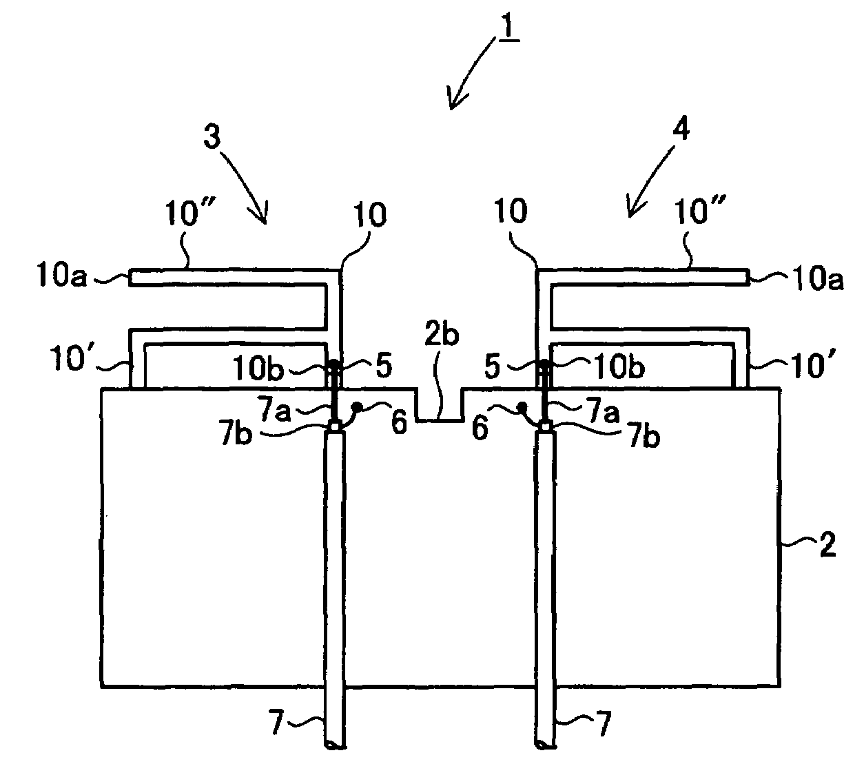
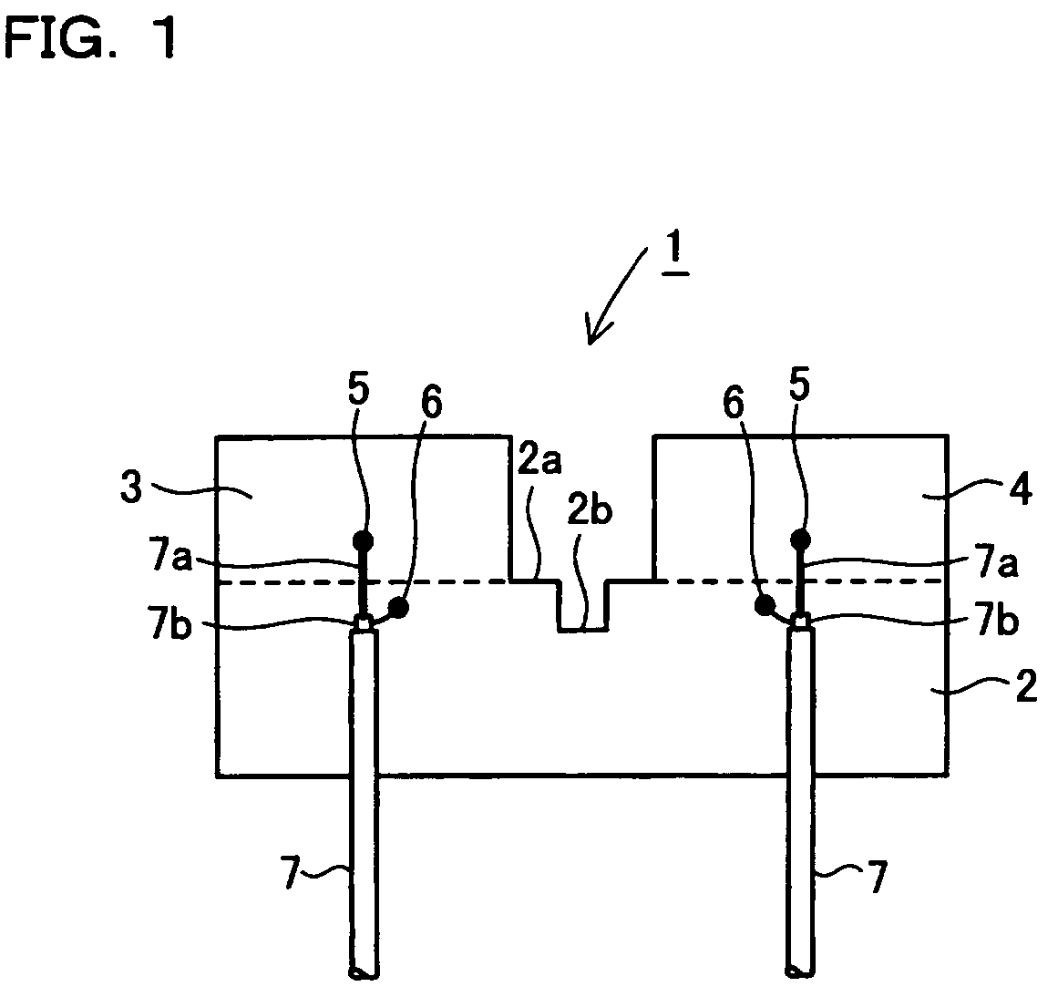
[0024]Preferred embodiments of an integrated multi-element planar antenna according to the present invention will be described below with reference to the drawings. FIG. 1 is a schematic block diagram showing an integrated multi-element planar antenna according to a first preferred embodiment of the present invention. As shown in FIG. 1, the integrated multi-element planar antenna according to the first non-limiting embodiment of the present invention has a ground pattern 2, first radiating element 3, and second radiating element 4. The ground pattern 2, for example, is rectangular in shape and has a notch 2b at an end 2a on one flank. The first radiating element 3 is placed on one side of the notch 2b, and the second radiating element 4 on the other side. Specifically, the first radiating element 3 and second radiating element 4 are formed at the end 2a on one flank of the ground pattern 2 and the notch 2b is located between the first radiating element 3 and second radiating elemen...


PUM


Abstract

An antenna consisting of a single small and lightweight package, where each radiating element operates independently with reduced interference among the radiating elements. An integrated multi-element planar antenna includes a ground pattern 2 with a notch 2b formed at an end 2a, first radiating element 3 placed on one side of the notch 2b and equipped with a feeder 5, and second radiating element 4 placed on the other side of the notch 2b and equipped with a feeder 5. For example, inverted F antennas are used as the first radiating element 3 and second radiating element 4. The first radiating element 3 and second radiating element 4 are placed symmetrically about the notch 2b such that separation distance will be the largest at locations where their radiation fields are the highest.

Description

RELATED APPLICATION[0001]This application claims priority from Japanese patent application serial No. 2005-192363, filed Jun. 30, 2005.I. FIELD OF THE INVENTION[0002]The present invention relates to an integral-type planar antenna equipped with multiple radiating elements adapting to the same frequency band. More particularly, it relates to an integral-type planar antenna with reduced mutual interference among multiple antenna elements.II . BACKGROUND OF THE INVENTION[0003]As transmission techniques for increasing communications speed of wireless LANs, MIMO / SDM (Multiple Input Multiple Output / Space Division Multiplexing), MIMO / SM (Multiple Input Multiple Output / Spatial Multiplexing), and other MIMO communications systems are considered promising. In simultaneous communication, by installing multiple transmitting antennas and receiving antennas, assigning different channels in the same frequency band to different transmitting antennas, and transmitting different sequences of signals ...

Claims


Application Information

Patent Timeline
Patent Type & Authority Patents(United States)
IPC IPC(8): H01Q1/38H01Q5/10
CPCH01Q21/28H01Q9/0407H01Q9/42H01Q5/371
Inventor FUJIO, SHOHHEIMASUDA, KAZUOASANO, TAKESHITSUMITA, MASAHIROKINUGASA, MASAKI
Owner LENOVO PC INT
Why Eureka
Try Eureka