

Cooling device for motor
A technology for cooling devices and cooling components, which is applied in the direction of cooling/ventilation devices, electromechanical devices, electrical components, etc., and can solve problems such as poor cooling effect and reduced electromagnetic performance of motors
- Summary
- Abstract
- Description
- Claims
- Application Information
AI Technical Summary
Problems solved by technology
Method used
Image

Examples
Embodiment 1
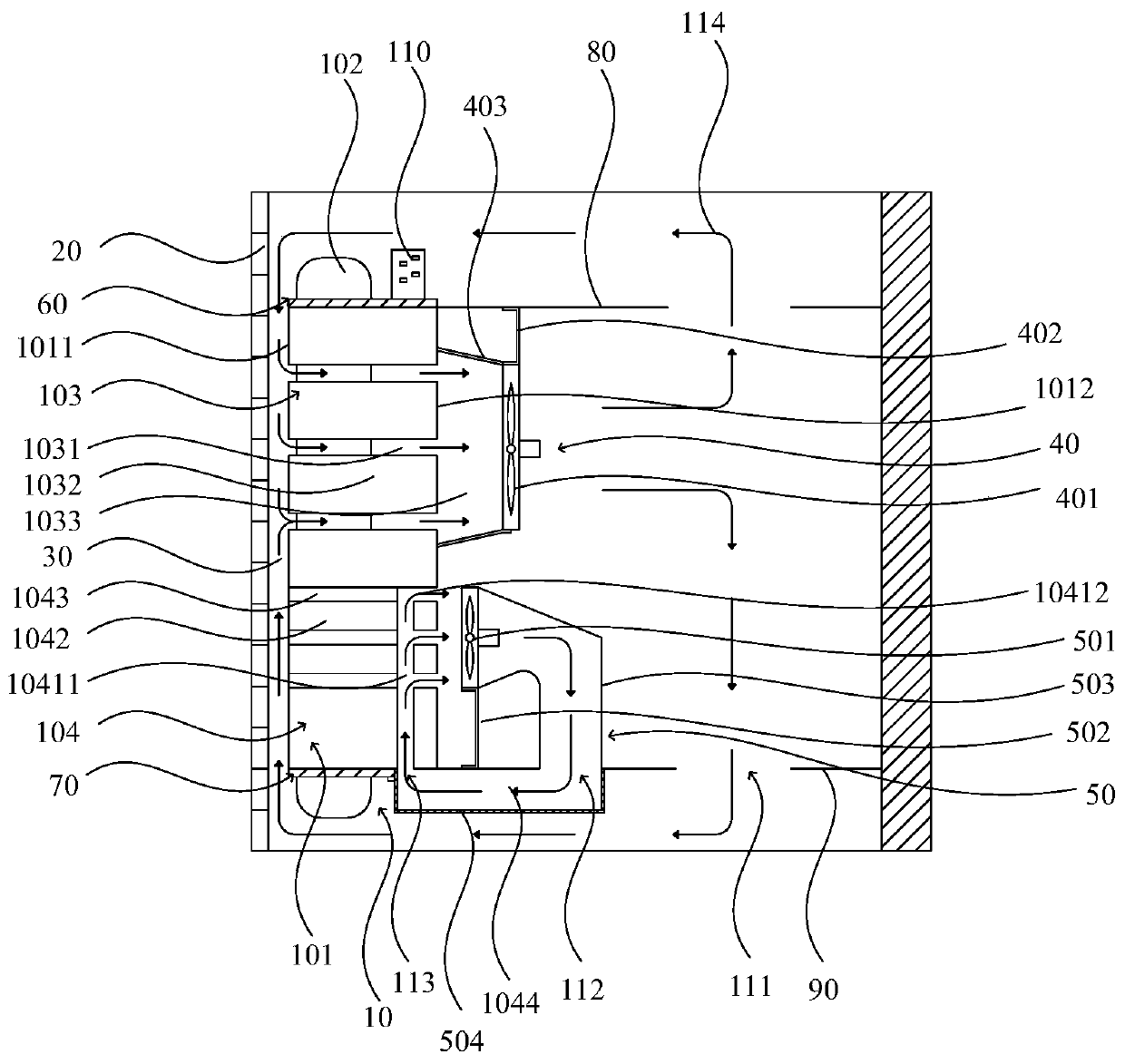
[0103] The invention provides a cooling device for a motor, such as Figure 1-4 As shown, the motor includes an inner stator 10 , an outer rotor 20 and an air gap 30 between the inner stator 10 and the outer rotor 20 , and the inner stator 10 includes a stator core 101 and a stator winding 102 . Along the axial direction of the motor, the stator core 101 includes a first axial section 103 and a second axial section 104, the first axial section 103 adopts radial cooling, the second axial section 104 adopts axial cooling, and the cooling medium All are air. In other alternative implementations, air is not limited to be used as the cooling air 114 , and other gases capable of cooling may also be used.
[0104] The cooling device of the motor includes a first cooling assembly 40 and a second cooling assembly 50 . The first cooling assembly 40 is arranged on the first axial section 103, and is used to form a first cooling channel to pass through the cooling air 114. The first coo...
Embodiment 2
[0127] The structure of this embodiment is basically the same as that of Embodiment 1, except that the structure of the second cooling assembly 50 is different, and the cooling medium of the second cooling assembly 50 is different.
[0128] Such as Figure 5 As shown, the second axial section 104 is cooled by liquid cooling, and the cooling medium is liquid. The second cooling assembly 50 includes a plurality of axial ventilation passages 1041 and a plurality of liquid cooling tubes 505, the plurality of liquid cooling tubes 505 are arranged at intervals along the circumferential direction of the motor, and the plurality of liquid cooling tubes 505 are passed through the corresponding axial ventilation channels. Inside Road 1041. Any liquid cooling pipe 505 is a U-shaped pipe structure, which facilitates the flow of cooling liquid, and any liquid cooling pipe 505 includes two cooling sections 5051 arranged in two adjacent axial air ducts 1041 and used to connect and communica...
Embodiment 3
[0131] The structure of this embodiment is basically the same as that of Embodiment 1, except that the structure of the third stack 1043 is different and the shape of the liquid cooling tube 505 is different.
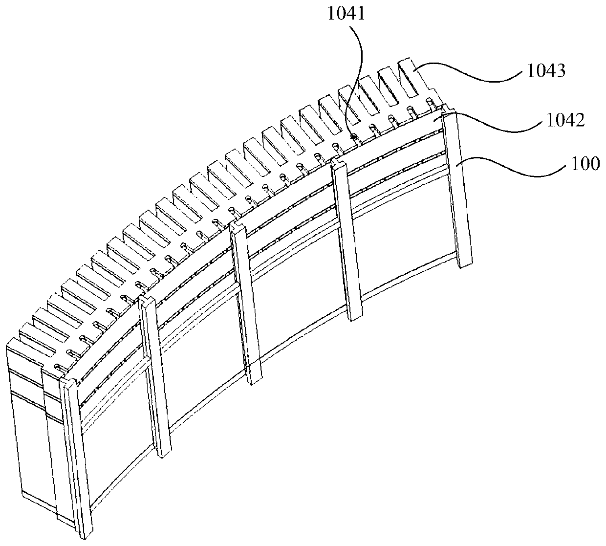
[0132] Such as Figure 6 As shown, the length of the yoke of the third lamination set 1043 is smaller than the length of the yoke of the second lamination set 1042 , and the axial ventilation channel 1041 is disposed inside the third lamination set 1043 . The axial direction of the connecting section 5052 is parallel to the axial direction of the cooling section 5051 .
PUM
 Abstract
Description
Claims
Application Information