Spatial prediction based intra coding

a prediction and spatial technology, applied in the field of image coding, can solve the problems of reconstructed frame and original frame difference, inability to render real-time image transmission, and high transmission bit rate,

Active Publication Date: 2007-10-30
NOKIA TECHNOLOGLES OY
View PDF5 Cites 83 Cited by
  • Summary
  • Abstract
  • Description
  • Claims
  • Application Information

AI Technical Summary

Benefits of technology

[0048]A method and device for coding a digital image using intra-mode block prediction is provided. A list of prediction modes for each combination of prediction modes of the neighboring blocks is obtained. The modes assigned to each combination of prediction modes may be divided into two groups. The first group includes m (where m is smaller than the overall number n of available modes) most probable prediction modes and the second group includes the remaining modes. The modes in the first group are ordered according to their probability. This order may be specified as a list of modes ordered from most probable to the least probable mode. The modes belonging to the second group may be ordered in some predetermined manner, which may be specified depending on the information already available to the decoder. Information is sent to the decoder regarding whether the mode selected for a given block belongs to the first group or to the second group. If it belongs to the first group, the information is transmitted indicating that ith most probable mode shall be used for a block C given the combination of modes for blocks U and L. If the mode belongs to the second group, the information is transmitted indicating that jth mode of this group should be used.

Problems solved by technology

Without compression, the quantity of information to be conveyed from an image encoder to an image decoder is so enormous that it renders real-time image transmission impossible.
However, pure block-based coding only reduces the inter-pixel correlation within a particular block, without considering the inter-block correlation of pixels, and it still produces high bit-rates for transmission.
The difference between the reconstructed frame and the original frame is called reconstruction error.
The above-mentioned method has one major drawback—the memory required to keep ordering of prediction modes for block C given prediction modes of blocks U and L is demanding.

Method used


Image

  • Spatial prediction based intra coding
  • Spatial prediction based intra coding
  • Spatial prediction based intra coding

Examples


Embodiment Construction

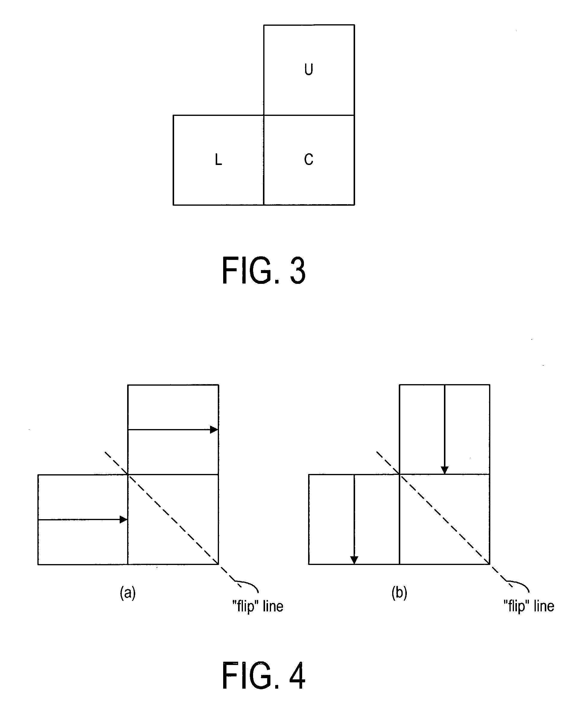
[0060]An embodiment of the present invention utilizes the property that it is possible to obtain an ordered list of prediction modes for one combination of prediction modes of neighboring blocks as a function of prediction modes for another combination. For illustration purposes, prediction modes of two neighboring blocks U and L, as shown in FIG. 3, are used to infer the prediction of the current block C. It is noted that a combination of prediction modes in FIG. 4a can be obtained by flipping diagonally the prediction modes, as shown in FIG. 4b. Accordingly, the nth most probable prediction mode for block C, when the combination of modes in FIG. 4a is used, should be the same as the “flipped diagonally”, nth-most-probable prediction mode for the combination of modes in FIG. 4b. Thus, if the neighboring blocks U and L have the modes “vertical” and “vertical”, the prediction mode of the current block C is most probably “vertical” (FIG. 4b). Consequently, when these blocks are “flipp...


PUM


Abstract

A method and device for coding a digital image using intra-mode block prediction, wherein a list of prediction modes for each combination of prediction modes of the neighboring blocks is obtained. The modes assigned to each combination of prediction modes may be divided into two groups. The first group includes n (where n is smaller than the overall number of available modes) most probable prediction modes and the second group includes the remaining modes. The modes in the first group are ordered according to their probability. This order may be specified as a list of modes ordered from most probable to the least probable mode. The modes belonging to the second group may be ordered in some predetermined manner, which may be specified depending on the information already available to the decoder.

Description

[0001]This application is a Continuation-In-Part and claims the benefit of a copending U.S. patent application Ser. No. 10 / 171,467, filed Jun. 12, 2002, assigned to the assignee of the instant application. This application is also based on and claims priority under 35 U.S.C. § 119(e) to U.S. provisional patent applications Ser. No. 60 / 388,061, filed Jun. 11, 2002, Ser. No. 60 / 391,112, filed Jun. 21, 2002, and Ser. No. 60 / 395,178, filed Jul. 9, 2002.FIELD OF THE INVENTION[0002]The present invention relates generally to image coding and, more particularly, to coding blocks of video frames.BACKGROUND OF THE INVENTION[0003]A digital image, such as a video image, a TV image, a still image or an image generated by a video recorder or a computer, consists of pixels arranged in horizontal and vertical lines. The number of pixels in a single image is typically in the tens of thousands. Each pixel typically contains luminance and chrominance information. Without compression, the quantity of i...

Claims


Application Information

Patent Timeline
Patent Type & Authority Patents(United States)
IPC IPC(8): G06K9/36G06K9/46H04N7/26H04N19/593
CPCH04N19/197H04N19/105H04N19/463H04N19/196H04N19/593H04N19/176
Inventor KARCZEWICZ, MARTA
Owner NOKIA TECHNOLOGLES OY
Why Eureka
Try Eureka