
Multiview video decomposition and encoding

a multi-view video and decomposition technology, applied in the field of video encoding, can solve the problems of not relating the different camera views, and the method cannot be applied directly to multi-view video encoding

Inactive Publication Date: 2008-12-23
MITSUBISHI ELECTRIC RES LAB INC
View PDF0 Cites 27 Cited by
  • Summary
  • Abstract
  • Description
  • Claims
  • Application Information

AI Technical Summary

Benefits of technology

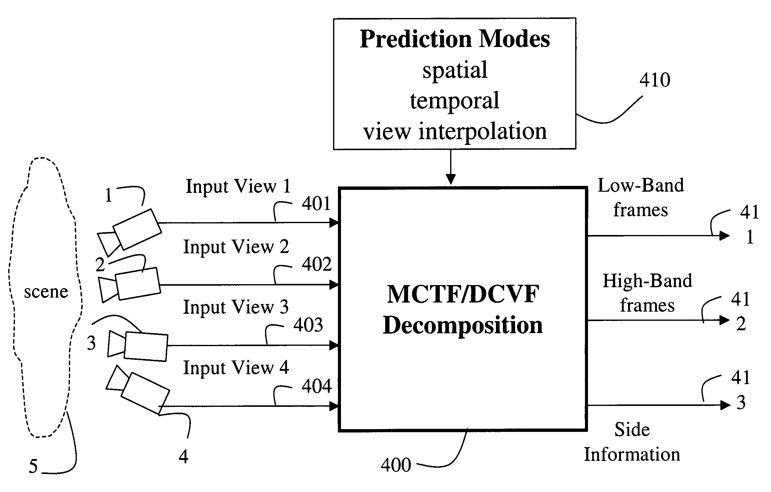
The patent describes a way to break down videos from multiple cameras that capture a scene. The method selects between three different modes for predicting the video content: temporal, spatial, and view interpolation. The videos are then broken down into low and high band frames, as well as side information. The method can also interpolate the videos to create a new view of the scene. The technical effect is a more efficient way to analyze and process multiple camera footage.

Problems solved by technology

However, that system does not correlate the different camera views.
However, that method cannot be applied directly to multiview video coding in which a correlation between the multiple views is exploited because there is no efficient method for predicting views that also accounts for correlation in time.
However, that method cannot be applied directly to multiview video encoding in which both the temporal correlation and correlation between views are exploited because there is no efficient method for predicting views that also accounts for correlation in time.

Method used


Image

  • Multiview video decomposition and encoding
  • Multiview video decomposition and encoding
  • Multiview video decomposition and encoding

Examples


first embodiment

[0035]In a first embodiment, the MCTF and DCVF are applied adaptively on a block-basis to the frames of the input views to yield a decomposed set of low band frames, as well as high band frames, and the associated side information. In this way, each block selects adaptively a best multiview mode of prediction among the available multiview modes described above. An optimal method for selecting the multiview mode is described below.

second embodiment

[0036]In a second embodiment, the MCTF is first applied to the frames of each camera view independently. The resulting frames are then further decomposed with the DCVF. In addition to the final decomposed frames, the corresponding side information is also generated. If performed on a block-basis, the prediction mode selections for the MCTF and the DCVF are considered separately. As an advantage, this mode selection inherently supports temporal scalability. In this way, lower temporal rates of the videos are easily accessed in the compressed bitstream.

third embodiment

[0037]In a third embodiment, the DCVF is first applied to the frames of the input views. The resulting frames are then temporally decomposed with the MCTF. In addition to the final decomposed frames, side information is also generated. If performed on a block-basis, the prediction mode selections for the MCTF and DCVF are considered separately. As an advantage, this selection inherently supports view scalability. In this way, a reduced number of the views are easily accessed in the compressed bitstream.

[0038]The decomposition described above can be applied recursively on the resulting set of low band frames from a previous decomposition stage. As an advantage, our MCTF / DCVF decomposition 400 effectively removes both temporal and inter-view (spatial) correlations and can achieve a very high compression efficiency. The compression efficiency of our multiview video encoder outperforms conventional simulcast encoding, which encodes each view independently from other views.

[0039]Coding o...


PUM


Abstract

A method decomposes multiview video acquired of a scene by multiple cameras. Each multiview video includes a sequence of frames, and each camera provides a different view of the scene. A prediction mode is selected from a temporal prediction mode, a spatial prediction mode, and a view interpolation prediction mode. The multiview videos are then decomposed into low band frames, high band frames, and side information according to the selected prediction mode.

Description

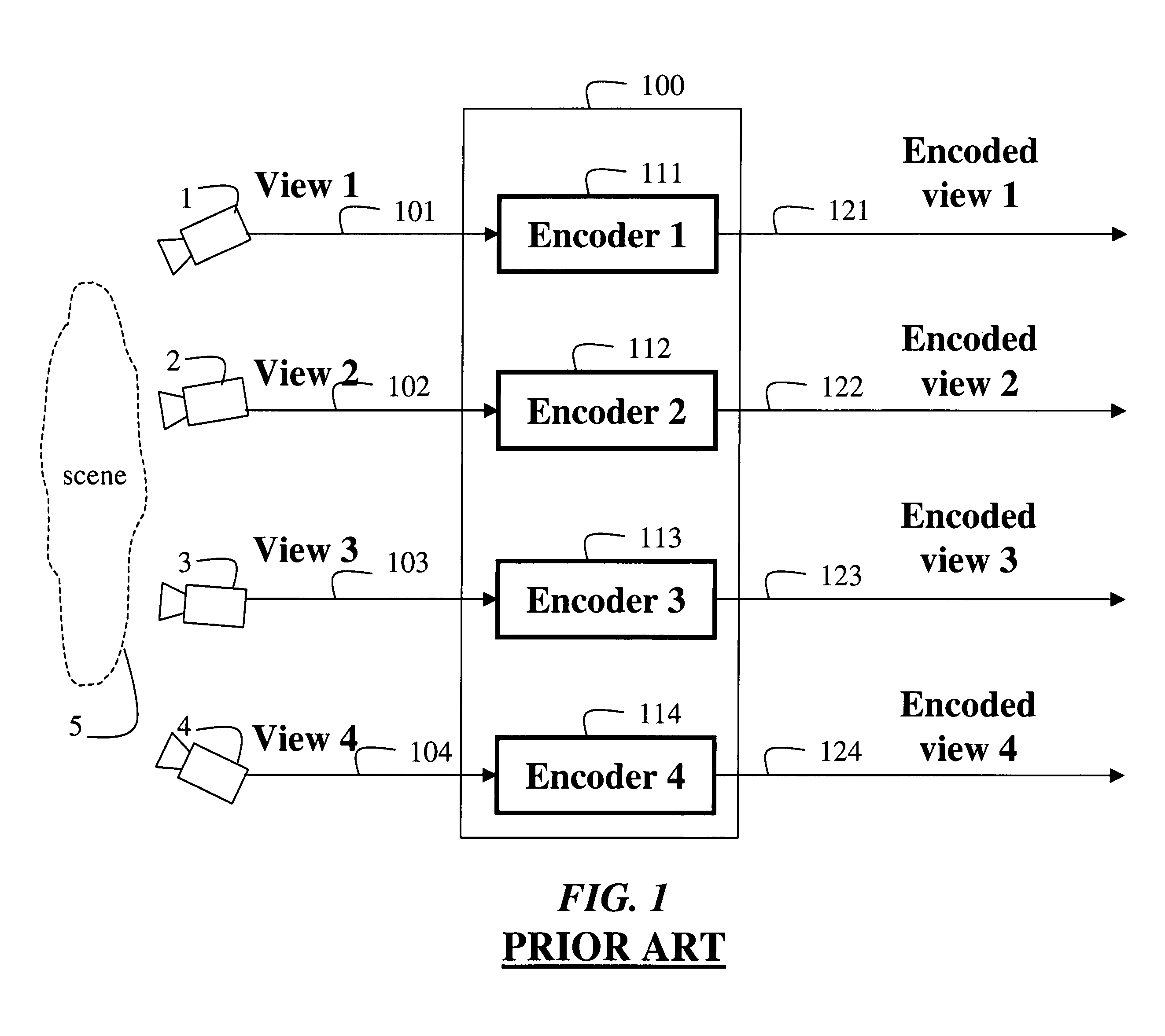
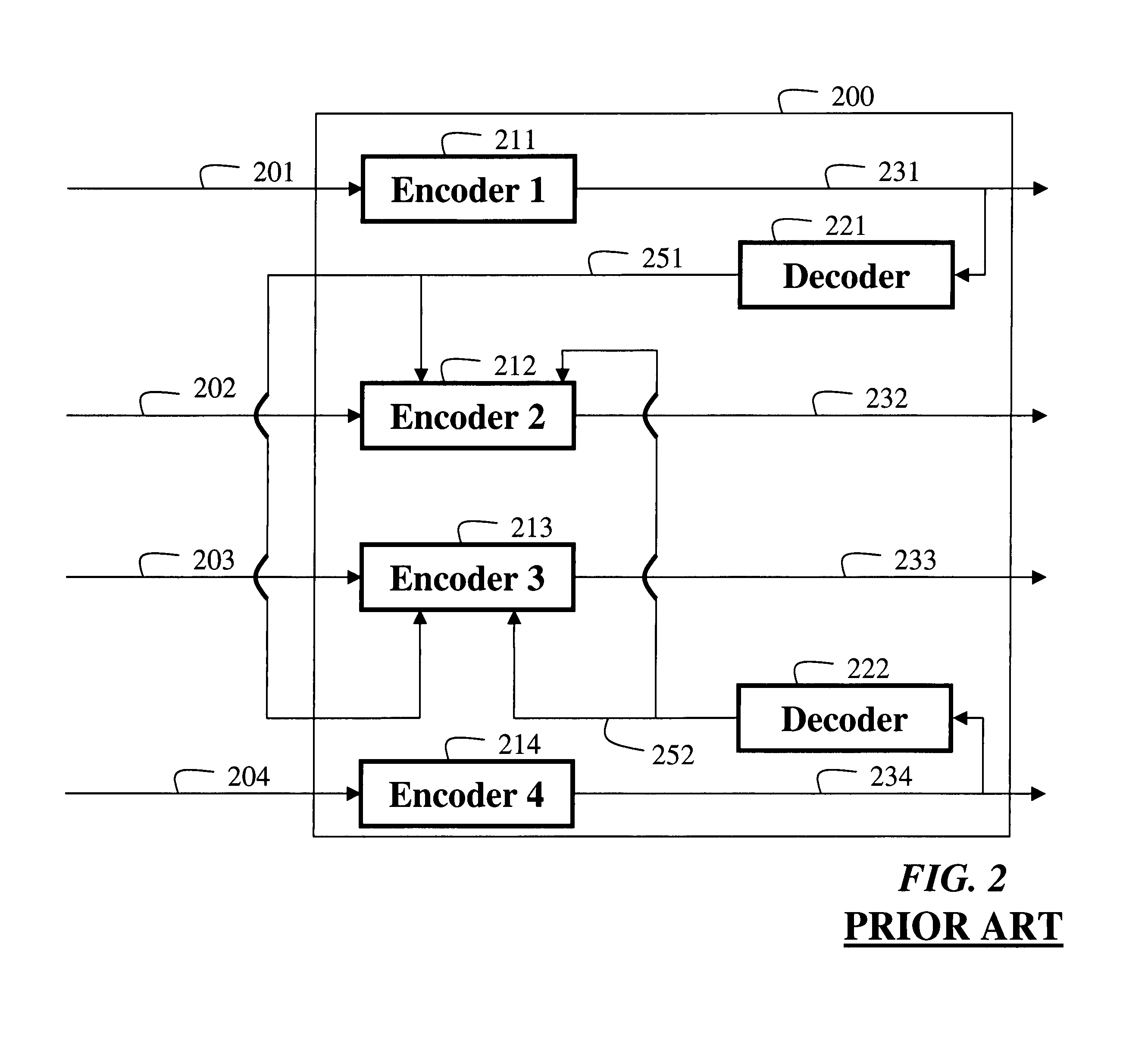
FIELD OF THE INVENTION[0001]This invention relates generally to video encoding, and more particularly to encoding multiview videos.BACKGROUND OF THE INVENTION[0002]Multiview video encoding is essential for applications such as 3D television (3DTV), free viewpoint television (FTV), and multi-camera surveillance. Multiview video encoding is also known as dynamic light field compression.[0003]FIG. 1 shows a prior art ‘simulcast’ system 100 for multiview video encoding. Cameras 1-4 acquire ‘views’101-104 of a scene, where the input views from each camera are typically time synchronized. The views are encoded 111-114 independently to corresponding encoded views 121-124. That system uses conventional 2D video encoding techniques. However, that system does not correlate the different camera views. Independent encoding decreases compression efficiency, and thus network bandwidth and storage are increased. For a large number of cameras, inter-view correlation would greatly increase the effic...

Claims


Application Information

Patent Timeline
Patent Type & Authority Patents(United States)
IPC IPC(8): H04N5/225
CPCH04N19/597H04N19/176H04N19/615H04N19/61H04N19/103H04N19/63H04N19/13
Inventor XIN, JUNMARTINIAN, EMINVETRO, ANTHONY
Owner MITSUBISHI ELECTRIC RES LAB INC
Learn More