System and process for compressing and decompressing multiple, layered, video streams of a scene captured from different viewpoints forming a grid using spatial and temporal encoding

a video stream and spatial and temporal encoding technology, applied in television systems, instruments, color signal processing circuits, etc., can solve the problems of synchronizing so many cameras, decompressing compressed data, and existing systems that do not allow users to interactively change to any desired viewpoints, etc., to achieve the effect of facilitating explanation

Active Publication Date: 2006-02-09
MICROSOFT TECH LICENSING LLC
View PDF3 Cites 29 Cited by
  • Summary
  • Abstract
  • Description
  • Claims
  • Application Information

AI Technical Summary

Benefits of technology

[0012] The present invention is directed toward a system and process for compressing and decompressing multiple video streams depicting substantially the same dynamic scene. To facilitate the explanation of the present system and process, the multiple video streams can be characterized as being video data that is made up of sequential sets of contemporaneous video frames. Each frame in a set depicts substantially th...

Problems solved by technology

Unfortunately, this effect is a one-time, pre-planned affair.
Thus, existing systems would not allow a user to interactively change to any desired viewpoint while watching a dynamic image-based scene.
However, extending IBR to dynamic scenes is not trivial because of, among other things, the difficulty (and cost) of synchronizing so many cameras and acquiring the images.
Compressing the video data to a workable size for transmission or storage, and then decompressing the compressed data in an efficient and quick manner with acceptable quality, is also a difficult problem.
Essentially, the amoun...

Method used


Image

  • System and process for compressing and decompressing multiple, layered, video streams of a scene captured from different viewpoints forming a grid using spatial and temporal encoding
  • System and process for compressing and decompressing multiple, layered, video streams of a scene captured from different viewpoints forming a grid using spatial and temporal encoding
  • System and process for compressing and decompressing multiple, layered, video streams of a scene captured from different viewpoints forming a grid using spatial and temporal encoding

Examples


Embodiment Construction

[0029] In the following description of the preferred embodiments of the present invention, reference is made to the accompanying drawings which form a part hereof, and in which is shown by way of illustration specific embodiments in which the invention may be practiced. It is understood that other embodiments may be utilized and structural changes may be made without departing from the scope of the present invention.

1.0 INTERACTIVE VIEWPOINT VIDEO

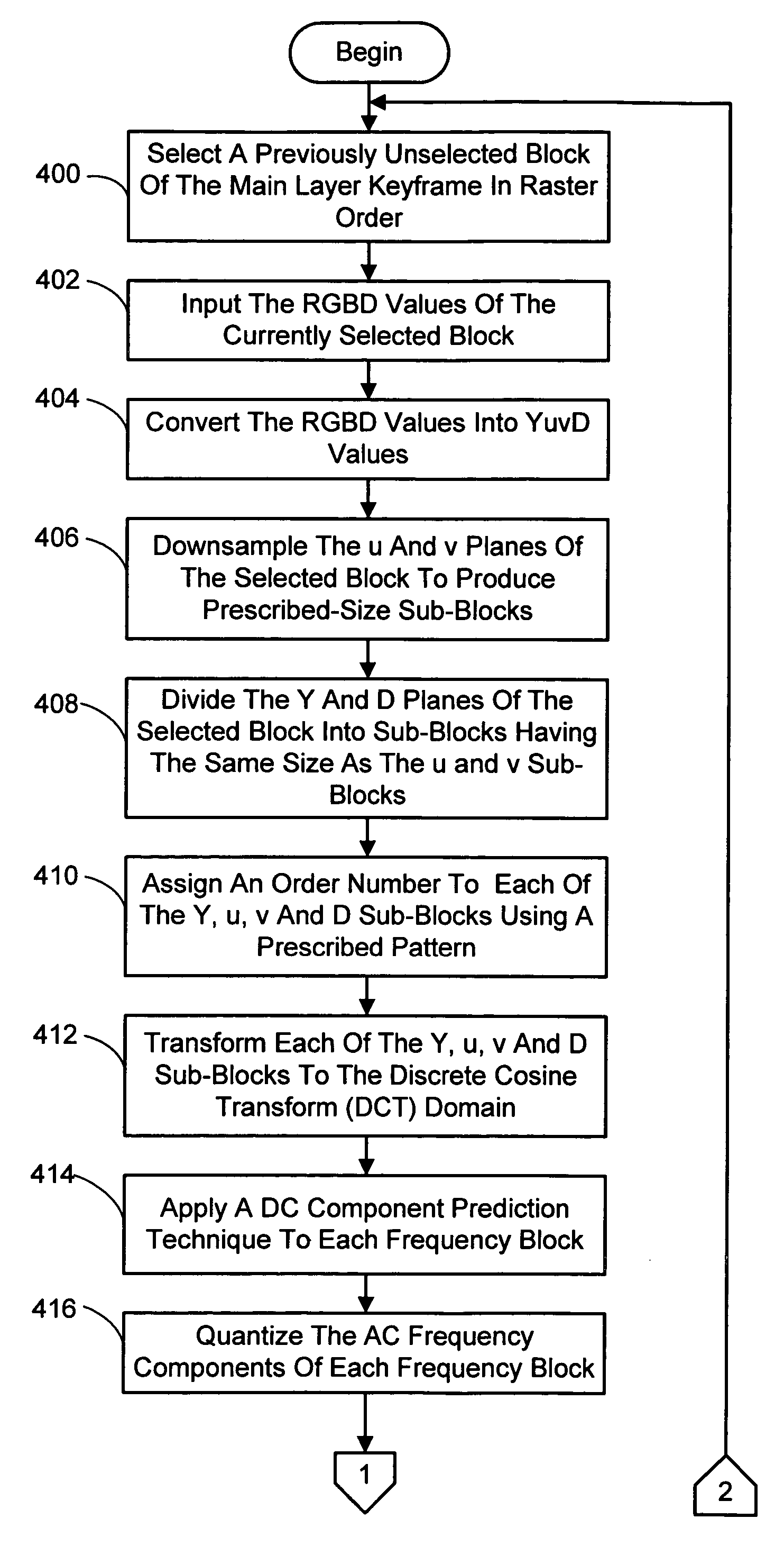
[0030] The present system and process is used to compress and decompress interactive viewpoint video data, or other data having the same video frame form. In general, interactive viewpoint video is video in which a user can watch a dynamic scene while manipulating (freezing, slowing down, or reversing) time and changing the viewpoint at will. This video is generated using a relatively small number of cameras to simultaneously capture multiple views of a scene from different viewpoints to produce a set of contemporaneous frames of the vide...


PUM


Abstract

A system and process for compressing and decompressing multiple video streams depicting substantially the same dynamic scene from different viewpoints that from a grid of viewpoints. Each frame in each contemporaneous set of video frames of the multiple streams is represented by at least a two layers—a main layer and a boundary layer. Compression of the main layers involves first designating one or more of these layers in each set of contemporaneous frames as keyframes. For each set of contemporaneous frames in time sequence order, the main layer of each keyframe is compressed using an inter-frame compression technique. In addition, the main layer of each non-keyframe within the frame set under consideration is compressed using a spatial prediction compression technique. Finally, the boundary layers of each frame in the current frame set are each compressed using an intra-frame compression technique. Decompression is generally the reverse of the compression process.

Description

CROSS-REFERENCE TO RELATED APPLICATIONS [0001] This application is a continuation-in-part of a prior application entitled “A System And Process For Compressing And Decompressing Multiple, Layered, Video Streams Employing Spatial And Temporal Encoding” which was assigned Ser. No. 10 / 910,077 and filed Aug. 3, 2004.BACKGROUND [0002] 1. Technical Field [0003] The invention is related to compressing and decompressing video, and more particularly to a system and process for compressing and decompressing multiple, layered, video streams employing spatial and temporal encoding. [0004] 2. Background Art [0005] For several years now, viewers of TV commercials and feature films have been seeing the “freeze frame” effect used to create the illusion of stopping time and changing the camera viewpoint. The earliest commercials were produced by using a film-based system, which rapidly jumped between different still cameras arrayed along a rail to give the illusion of moving through a frozen slice o...

Claims


Application Information

Patent Timeline
IPC IPC(8): H04N7/16H04B1/66H04N11/04H04N11/02H04N7/12H03M7/30H04N19/50H04N19/60
CPCH04N13/0011H04N21/2365H04N21/4347H04N19/597H04N19/39H04N19/61H04N19/96H04N19/593H04N19/109H04N19/70H04N13/111H04N19/103H04N19/167H04N19/17H04N19/21H04N19/46
Inventor WINDER, SIMONUYTTENDAELE, MATTHEW T.ZITNICK, CHARLES LAWRENCE IIISZELISKI, RICHARDKANG, SING BING
Owner MICROSOFT TECH LICENSING LLC
Why Eureka
Try Eureka