Shoe suspension system
a suspension system and spring technology, applied in the field of boots and shoes, can solve the problems of inability to permit users to concurrently, ineffective and imprecise structures, and high cost and unreliability of spring shoes, and achieve the effects of optimum control, safety and agility, optimum traction stability, and mild internal roll capability
- Summary
- Abstract
- Description
- Claims
- Application Information
AI Technical Summary
Benefits of technology
Problems solved by technology
Method used
Image
Examples
embodiment 1
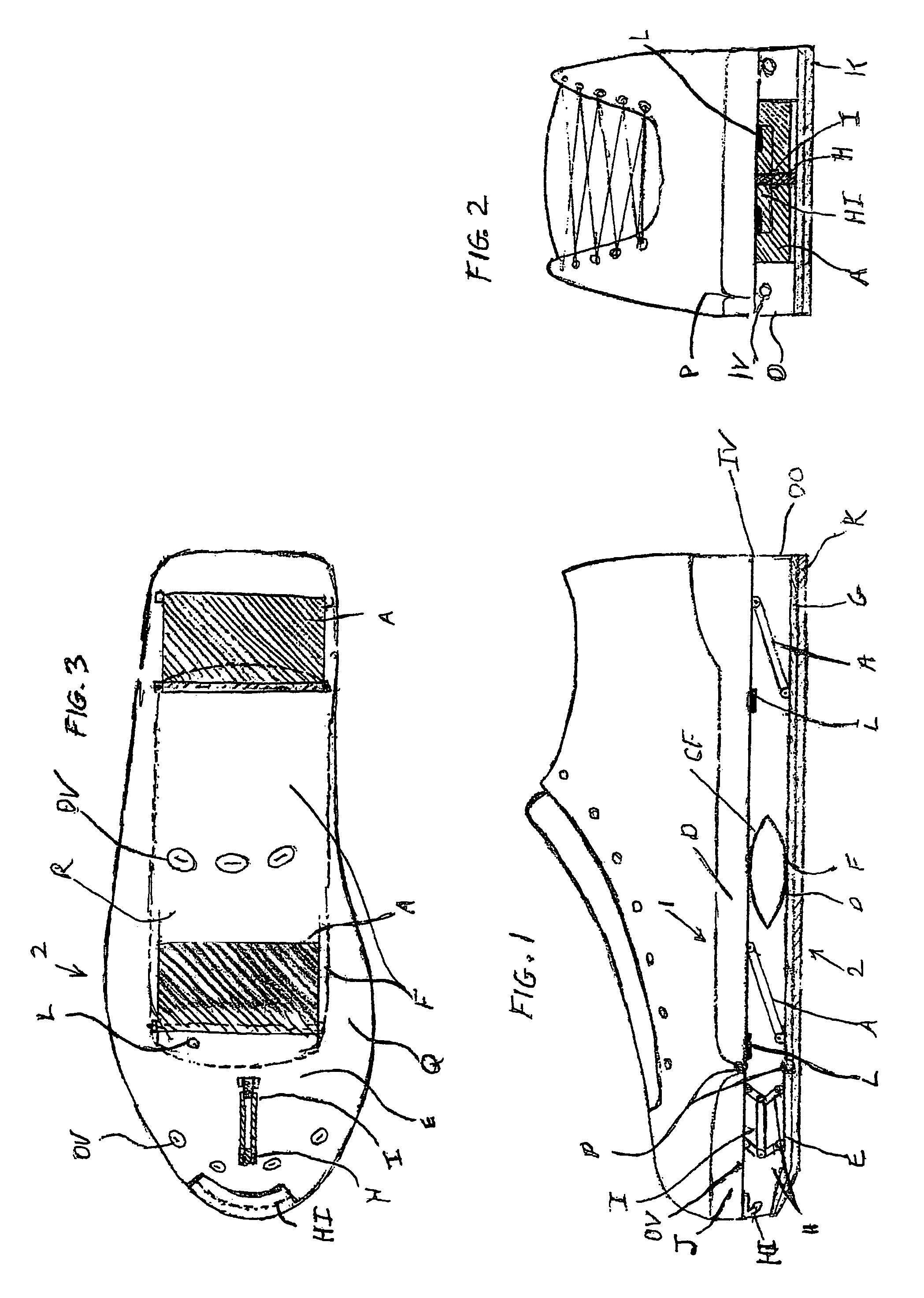
[0111]The lower sole (2) of embodiment 1 is patterned after the anatomy of the foot and ankle allowing users optimum traction, stability, control and safety. The lower sole provides for an integrated lower toe sole portion (E), lower mid sole portion (F), flexible outer portion (Q) of the mid sole (F) and lower heel sole (G) provides mild lateral roll capability.
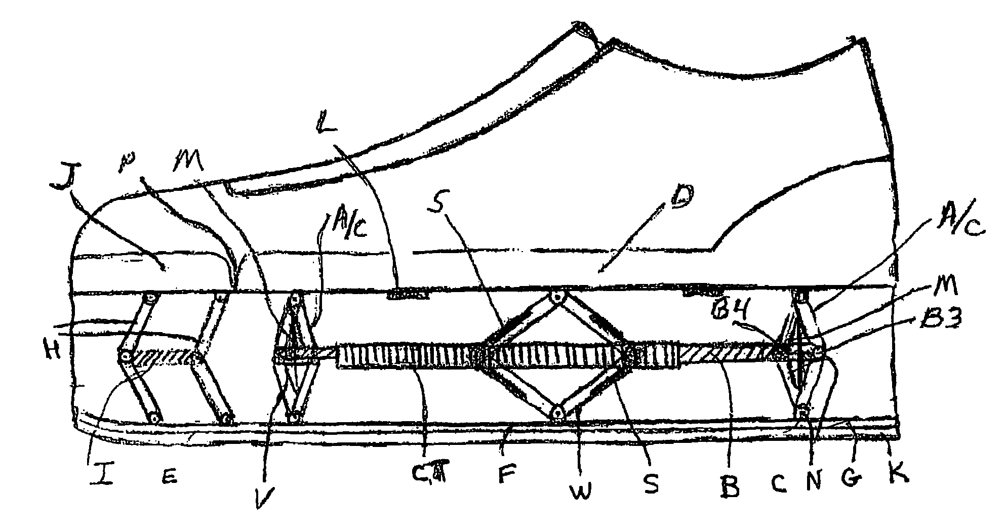
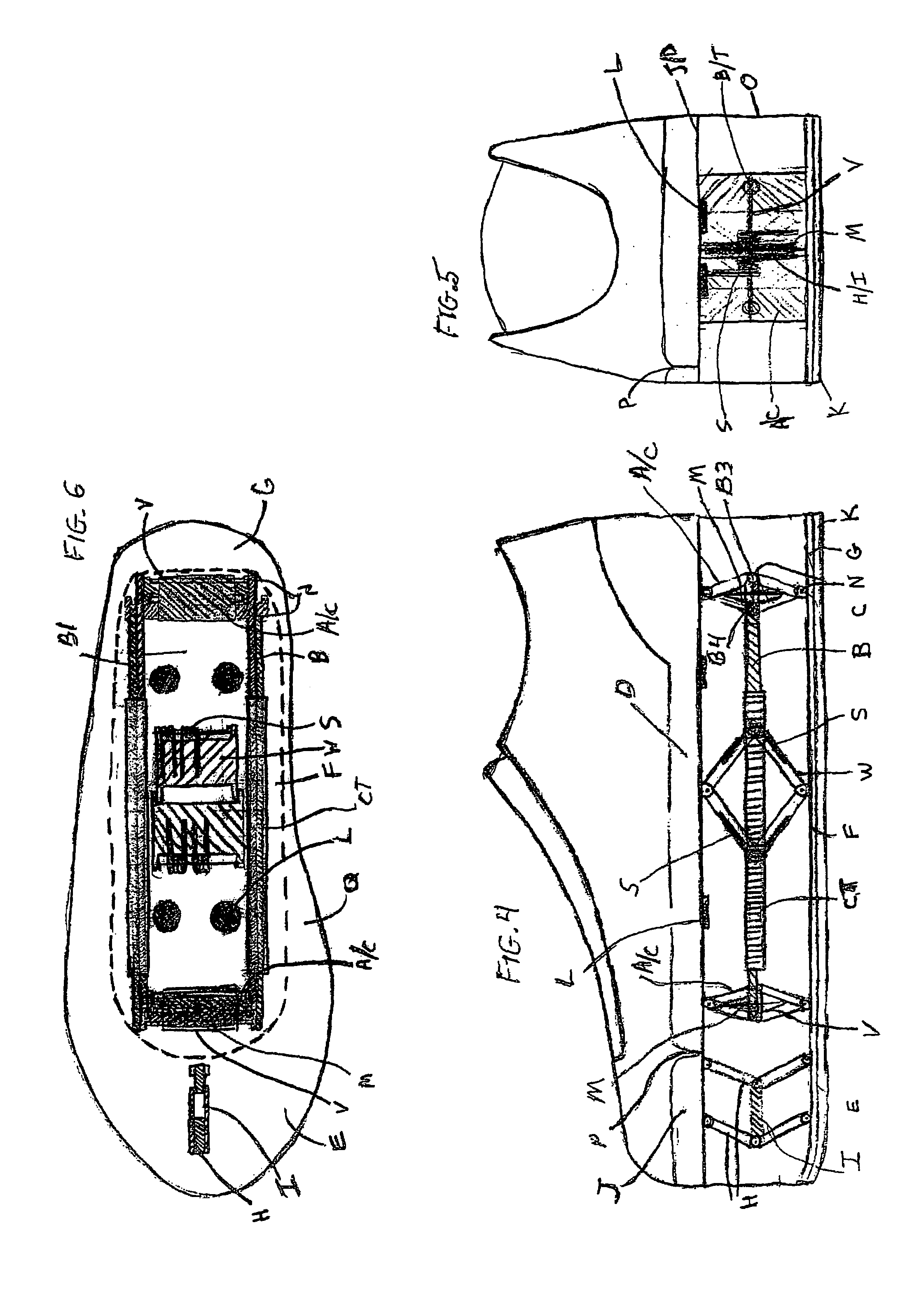
[0112]Embodiment 2 is a high performance running shoe for straight line running. Embodiment 2 as shown in FIGS. 4-6, also includes, as in embodiment 1, an upper sole (1), a lower sole (2), upper toe sole portion (J), upper mid heel sole portion (D), tread (K), a lower rigid inner section (F), a lower flexible outer section (Q), and a secondary tandem hinge (H) engaged between the lower sole (2) and the upper toe sole portion (J), and stops (L). The upper sole (1) includes a flex point (P) connecting an upper toe sole portion (J) to the upper mid / heel portion (D). These elements serve substantially the same purpose as the equ...
embodiment 3
[0117]In embodiment 3, the lower mid-sole (F) consists of an inflexible (e.g. steel), rectangular plate. The lower sole is connected to the tandem hinges by longitudinal pivots that allow lateral pivoting of the lower sole. A lateral support bumper (T) is inserted between the lower mid-sole (F) and the tandem hinge arm's hinge pin (X). An alternative structure can be used comprising of an inflexible rod connected at the ends to lower toe and heel soles via front and rear ball joints. This alternate structure also specifies a coil spring (CS) above the ball joint. The purpose of these structures is to: 1) provide traction to the user during mid-stride and 2) enhance balance and stability during mid-stride in a straight-line or in a turn.
[0118]All the primary and secondary tandem and opposing tandem hinges' (A), (A / C) and (H) have lower plates that are triangular in shape with their apex positioned at the lower toe / mid / heel soles (E), (F) and (G) where the apex attaches to the topside...
embodiment 4
[0124]In the high performance application of embodiment 4, the compressed spring load significantly exceeds a user's body weight. This system holds and releases (“HRS”) the energy stored in the springs at an optimum interval during accelerating, cruising or while decelerating. Utilizing this system, the performance benefit is roughly proportionate to the stored energy loads in excess of the user's body weight. Thus, this structure allows users to more than double their running stride and jumping performance compared to similar Embodiments without this system. This system is optimally designed in that it delivers: 1) Excellent control, 2) High running and jumping performance, 3) Safe deceleration / stopping, 4) A greater measure of running efficiency, allowing users to run longer distances while burning the same calories, 5) A completely natural running motion, which in-turn, further increases stability, reduces fatigue, and further increases performance and 6) A safety default to dise...
PUM
| Property | Measurement | Unit |
|---|---|---|
| diameter | aaaaa | aaaaa |
| diameter | aaaaa | aaaaa |
| diameter | aaaaa | aaaaa |
Abstract
Description
Claims
Application Information
 - R&D
- Intellectual Property
- Life Sciences
- Materials
- Tech Scout
- Unparalleled Data Quality
- Higher Quality Content
- 60% Fewer Hallucinations
Browse by: Latest US Patents, China's latest patents, Technical Efficacy Thesaurus, Application Domain, Technology Topic, Popular Technical Reports.
© 2025 PatSnap. All rights reserved.Legal|Privacy policy|Modern Slavery Act Transparency Statement|Sitemap|About US| Contact US: help@patsnap.com


