

Aerosol splitter for ELSD
a technology of elsd and splitters, applied in the direction of instruments, vessel construction, combustion types, etc., can solve the problem of not being able to control the split ratio, and achieve the effect of reducing the number of splits
- Summary
- Abstract
- Description
- Claims
- Application Information
AI Technical Summary
Problems solved by technology
Method used
Image

Examples
Embodiment Construction
—PREFERRED EMBODIMENT
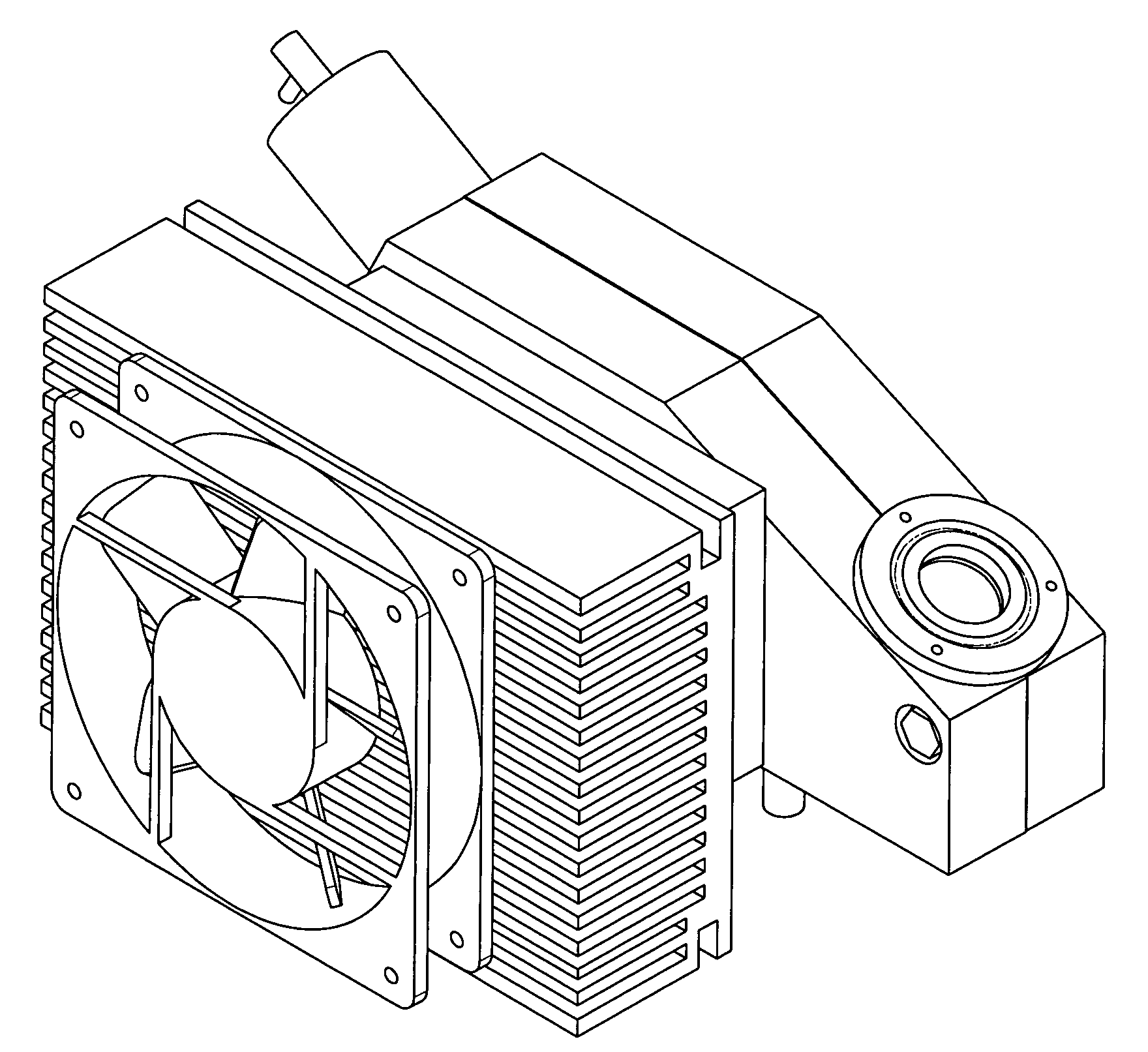
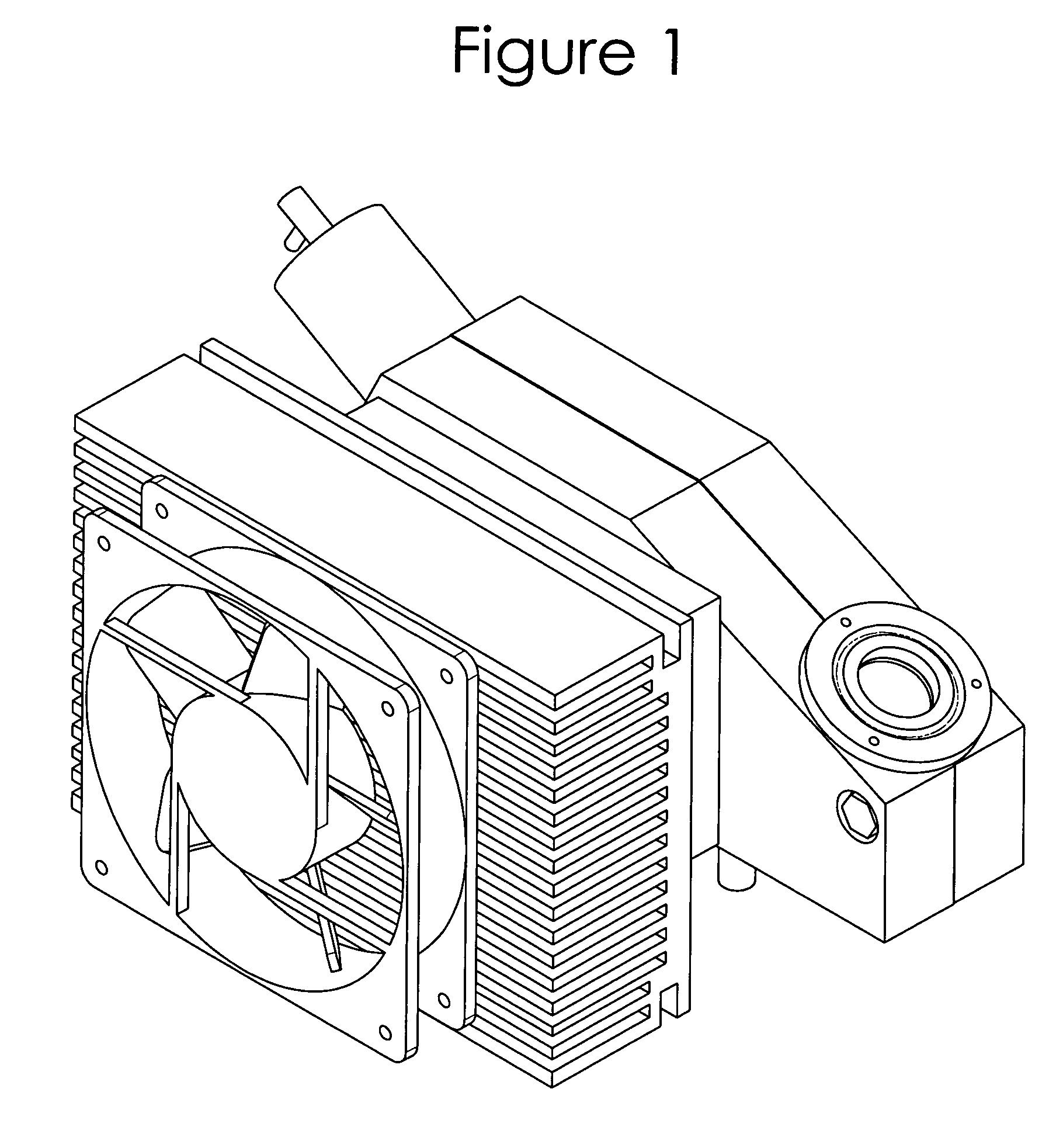
[0041]With principal reference to FIG. 2a, a preferred embodiment of the aerosol splitter is illustrated. The device comprises a nebulizer 12. The nebulizer is preferably an Elemental Scientific, Inc. model PFA-LC-2. The nebulizer 12 inserts into a Nebulizer Holder 14. The Nebulizer Holder 14 makes a gas tight connection between the Nebulizer 12 and the Spray Chamber 16. FIGS. 4a and 4b show the Nebulizer Holder in greater detail. FIG. 4b shows the grooves, which hold O-rings. These O-rings (not shown) make gas tight seals around both Nebulizer 12 and Spray Chamber 16.
[0042]The Spray Chamber 16 ultimately attaches to a Drift Tube 24 within the completed instrument, as illustrated in FIG. 5. To facilitate the attachment, the Spray Chamber 16 has a groove in the flange, which accommodates an O-ring (not shown). The O-ring allows for a gas tight connection while providing a measure of thermal isolation. Thermal isolation allows the Spray Chamber 16 and Drift Tube 2...
PUM
 Abstract
Description
Claims
Application Information