
Device that attaches to a surface

a technology of a device and a surface, applied in the direction of washstands, lighting support devices, ways, etc., can solve the problems of damage done by the load-bearing member, damage to the constructed surface and any coating, and can represent a major cost, and can cause malfunction and personal injury, malfunction and damag

Inactive Publication Date: 2007-11-06
ALVA IP I +2
View PDF14 Cites 17 Cited by
  • Summary
  • Abstract
  • Description
  • Claims
  • Application Information

AI Technical Summary

Problems solved by technology

The constructed surface itself can be easily chipped away around the hole becoming enlarged and unsightly, permanently damaging the constructed surface and any coating.
Thus, the damage done by the load-bearing member can represent a major cost over time in as much as constructed surfaces typically contain many such load bearing members scattered over the home, apartment, etc.
Another problem associated with the use of the load bearing members is that they are often long enough to be driven entirely through the constructed surface itself, that is, through the plaster, wallboard, etc., into ducting, pipes, electrical wiring and studs which can result in costly damage, malfunctions and personal injury.

Method used


Image

  • Device that attaches to a surface
  • Device that attaches to a surface
  • Device that attaches to a surface

Examples


Embodiment Construction

[0015]Turning to the drawings.

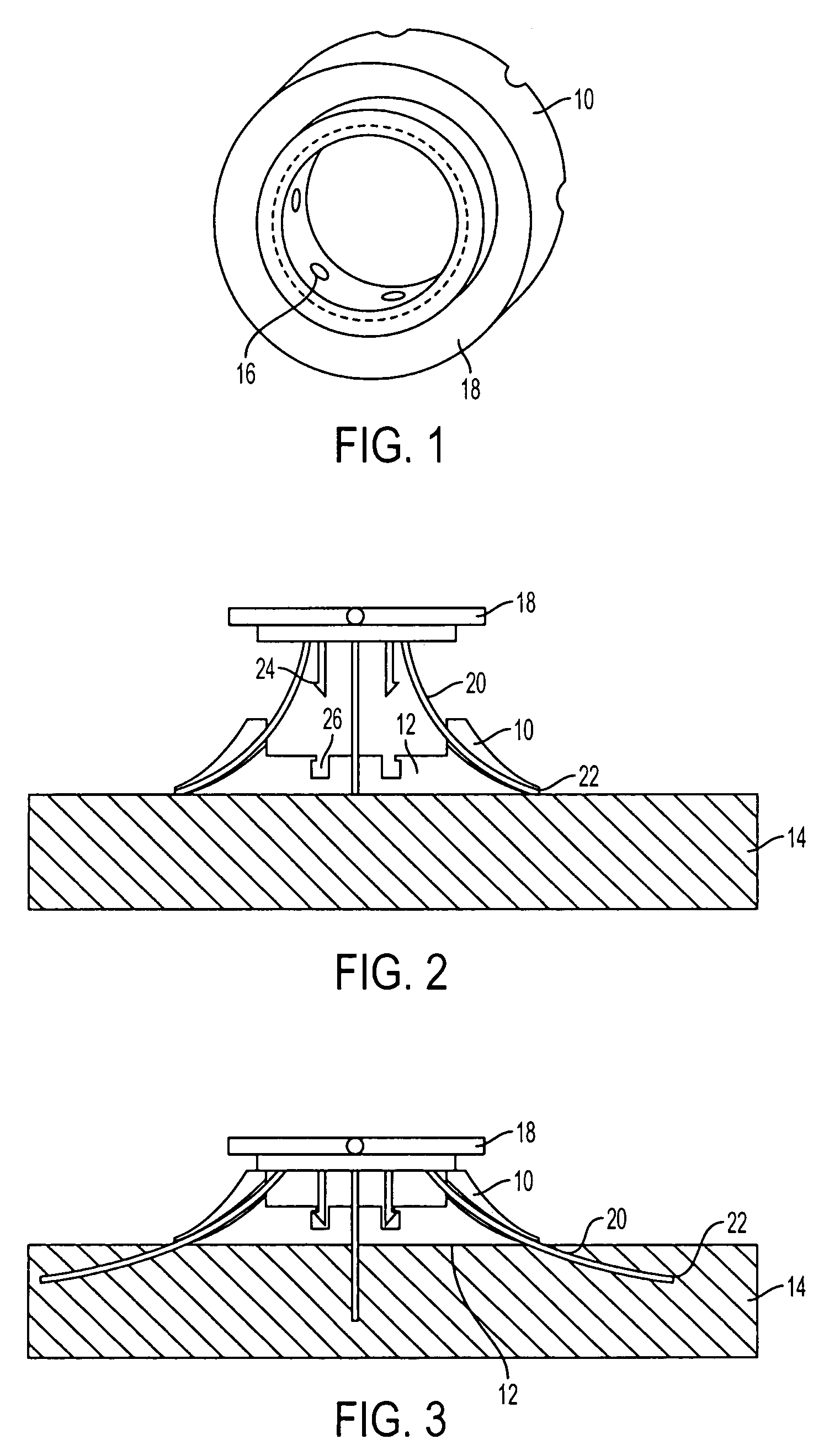
[0016]FIG. 1 is a perspective view of said first element.

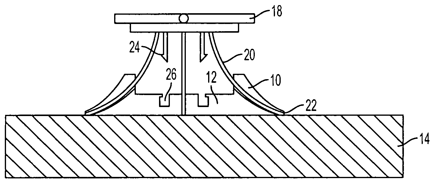
[0017]FIG. 2 is a side section view of the first and second element positioned such that one surface of the first element is flush with the constructed surface and the second element is ready to have force applied thereto to advance the plurality of tines in splayed fashion beyond the first element and into the constructed surface.

[0018]FIG. 3 shows the elements of FIG. 2 in section after the second element has been moved into proximity to the first element and the tines have been driven into the constructed surface.

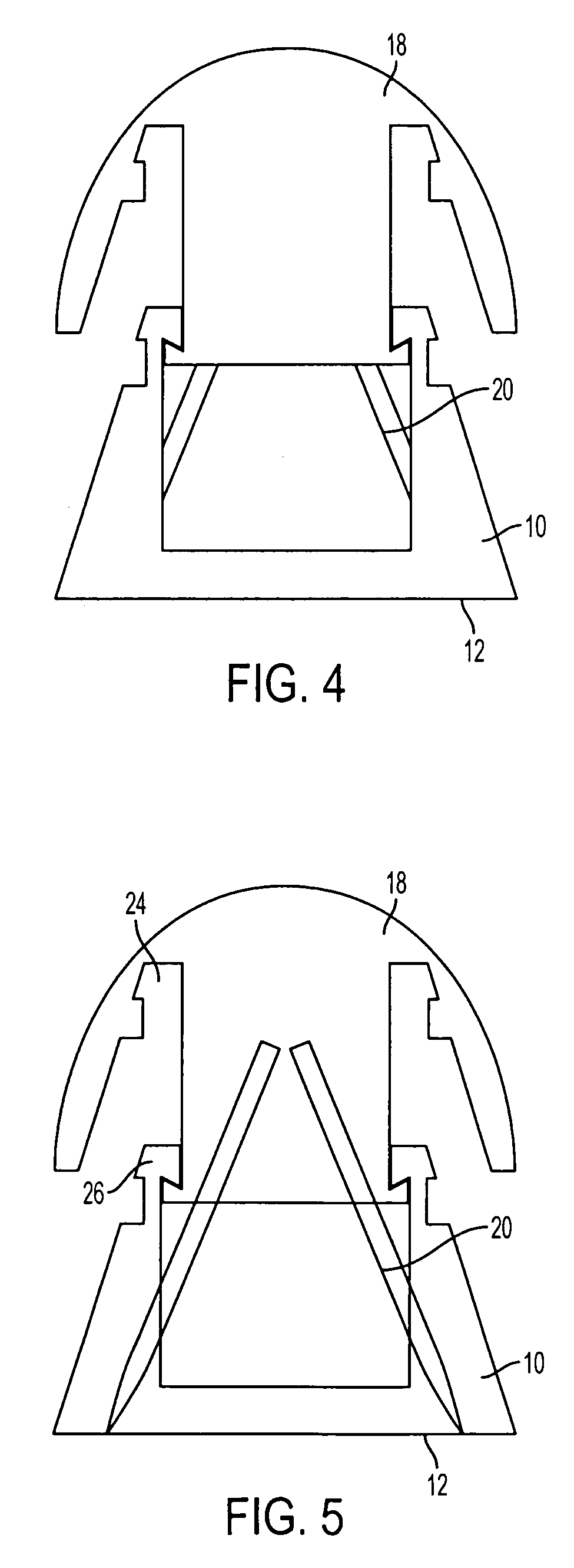
[0019]FIG. 4 is a side view of another embodiment of the invention, the second element of which has a domed outer surface, just prior to the movement of the second element toward the first element.

[0020]FIG. 5 is a side sectional view of the embodiment of FIG. 4.

[0021]FIG. 6 is a side view of the device of FIGS. 4 and 5 after the second element has been moved or pressed toward said fir...


PUM


Abstract

A device that attaches to a surface.A first element having a surface adapted to be carried flush with a surface of a constructed surface and having a plurality of splayed through openings therein.A second element adapted to be moved or pressed toward and held by the first element and having a plurality of tines joined to the second element in proximity to one extremity of the tines.The tines pass slidably through the splayed openings in the first element and have sharp penetrating ends which project into the constructed surface when the second element is moved toward first element and force is applied to the second element while the surface of the first element is flush with the constructed surface such that the first element comes affixed to the constructed surface by the tines.

Description

FIELD OF INVENTIONBackground of the Invention[0001]It is customary to drive load-bearing members such as nails, tacks, push pins, screws and the like into constructed surfaces to provide a fixed projection in order to attach or hang objects. For heavy loads, various types of bolts or brackets are often used.[0002]Constructed surfaces are usually made of plaster on lath, wallboard, sheetrock, wood, or cork; the nails, tacks, pins, screws, bolts or brackets, when pressed, driven or screwed into the constructed surface create holes in the constructed surface itself as well as any painted coating, wallpaper, wall finishing, or texture on the constructed surface. The constructed surface itself can be easily chipped away around the hole becoming enlarged and unsightly, permanently damaging the constructed surface and any coating.[0003]This is a matter of concern to the homeowner as well as to the tenant or lessee of an apartment, office or retail space since it becomes necessary to repair...

Claims


Application Information

Patent Timeline
Patent Type & Authority Patents(United States)
IPC IPC(8): F16B15/06A47G29/00
CPCA47G1/22F16B15/0053B43M15/00F16B15/04
Inventor NOWACK, CLIFFORD WILLIAM
Owner ALVA IP I
Learn More