
Method of deactivating device lock state, and electronic device

a technology of lock state and electronic device, which is applied in the field of electronic devices, can solve the problems of high level of secrecy, achieve the effect of simplifying the clear deactivation of lock state, and easy to use and learn

Inactive Publication Date: 2007-11-06
NOKIA TECH OY
View PDF9 Cites 46 Cited by
  • Summary
  • Abstract
  • Description
  • Claims
  • Application Information

AI Technical Summary

Benefits of technology

[0007]The method and device of the invention provide a plurality of advantages. The solution simplifies the deactivation of the lock state in a device. A touch screen lock can be deactivated rapidly without a keypad. The method is easy to use and learn.
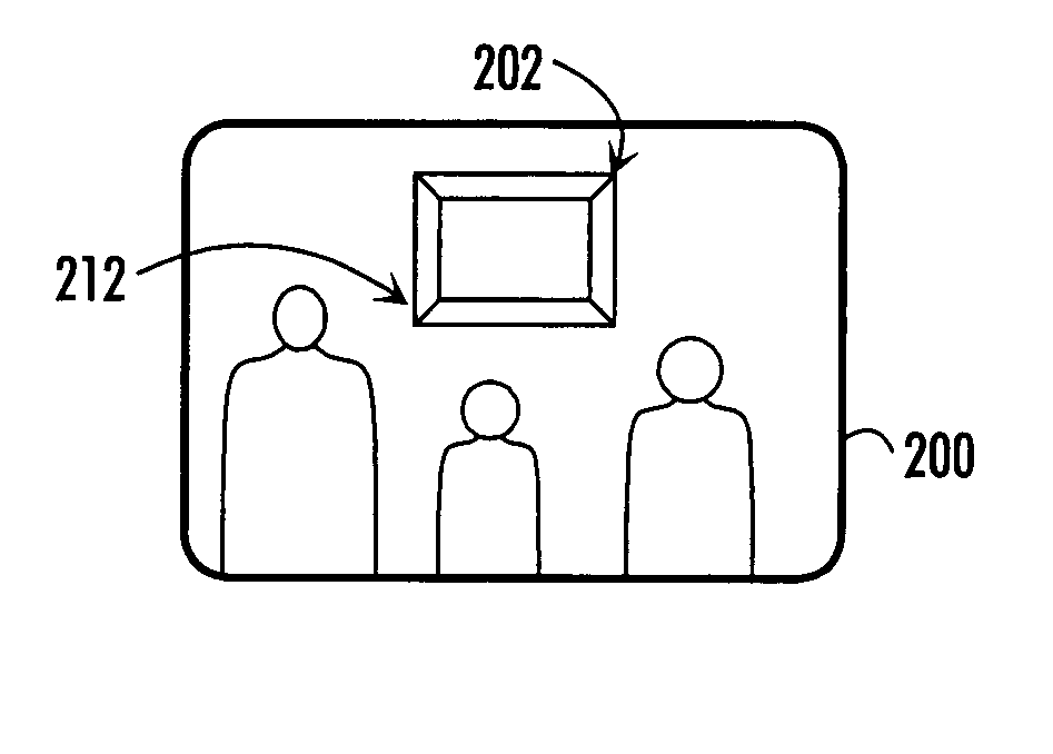
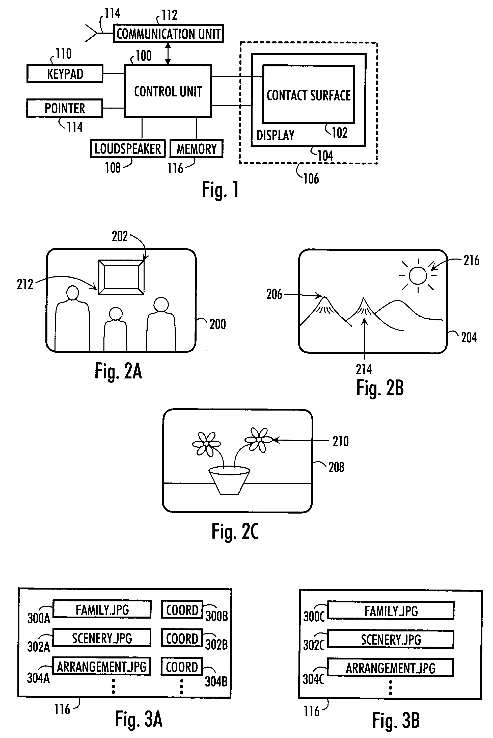
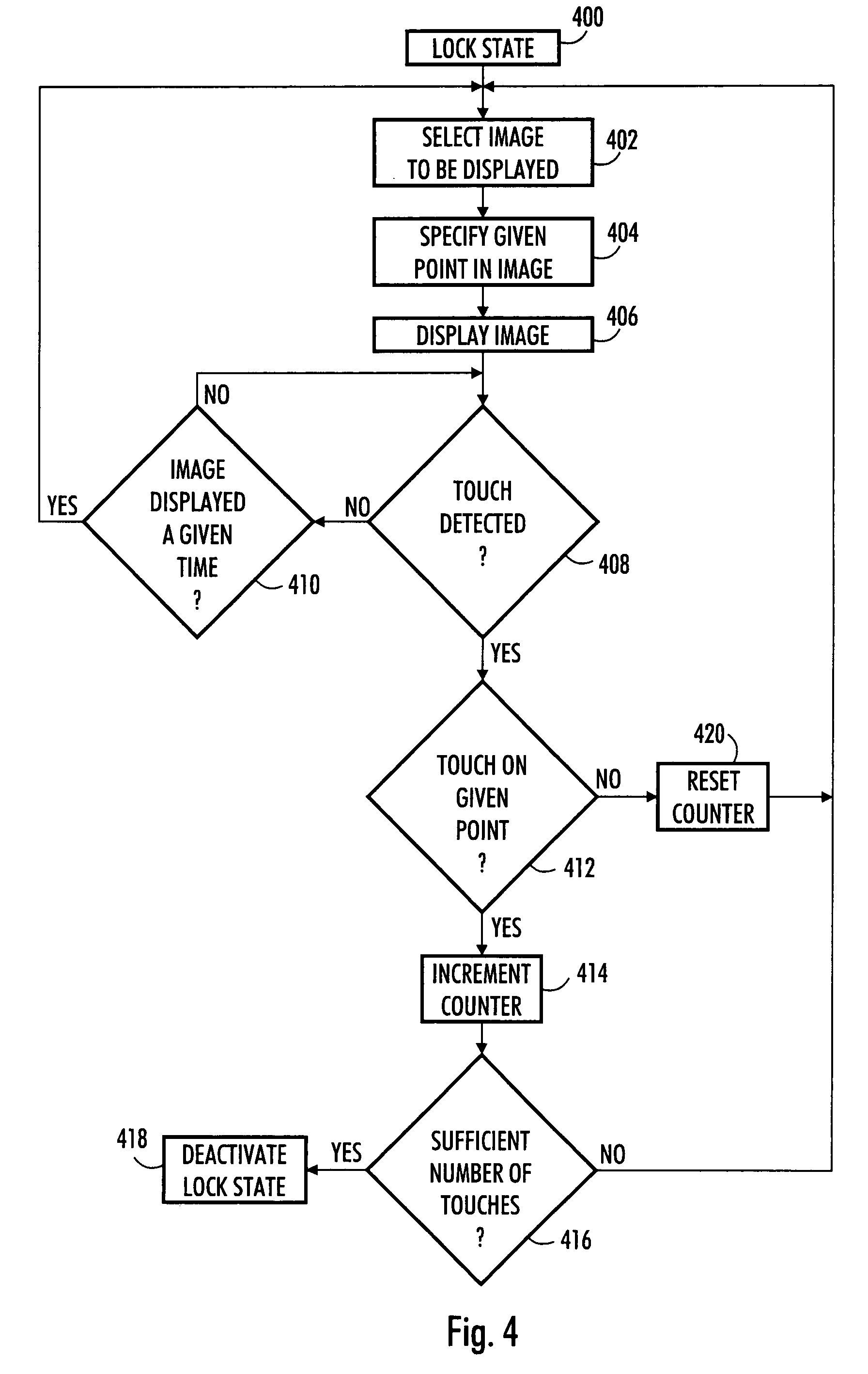
[0008]In a preferred embodiment, an image database is maintained in the device and the images are selected from it. The images include a given point, preferably selected by the user, which, when touched, performs a step in the deactivation of the lock state. When the device has detected touches on given points in images displayed in succession, the device deactivates the lock state and the device can again be used normally. The images are preferably selected by the user. Since both the images and the given point therein that has to be touched are selected by the user, the deactivation of the lock state is clearer than entering a password due to the visual property of the method, and thus easier for the user. However, secrecy remains on a high level, since the device lock state cannot be deactivated by touching the images at random.
[0009]In a preferred embodiment, the secrecy can be further improved in such a manner that the given point in the images changes adaptively depending on a parameter, such as the date.

Problems solved by technology

However, secrecy remains on a high level, since the device lock state cannot be deactivated by touching the images at random.

Method used


Image

  • Method of deactivating device lock state, and electronic device
  • Method of deactivating device lock state, and electronic device
  • Method of deactivating device lock state, and electronic device

Examples


Embodiment Construction

[0016]Preferred embodiments of the invention are applicable in electronic devices, such as a mobile station, used as a terminal in telecommunication systems including base stations and terminals communicating with the base stations. In some embodiments of the invention, the device includes means for short-range communication, implemented by means of a Bluetooth chip, an infrared or WLAN connection, for example. The electronic device is for instance a mobile telephone or another device including telecommunication means, such as a portable computer, a handheld computer or a smart telephone. The electronic device may also be a PDA (Personal Digital Assistant) device including telecommunication means for establishing a network connection, or a PDA device that can be coupled to a mobile telephone, for instance, for a network connection. Other alternatives include computers or PDA devices not including telecommunication means.

[0017]FIG. 1A shows a block diagram of the structure of a porta...


PUM


Abstract

An electronic device comprises a touch screen and is configured to enter a lock state upon the fulfilment of a predetermined condition. The device is configured to display one or more images on the touch screen when the device is in the lock state, of which images one or more includes at least one predetermined point. The device is further configured to detect a touch on a predetermined point in one or more images and to deactivate the device lock state upon detection of a predetermined number of touches on successive images including a predetermined point.

Description

FIELD[0001]The invention relates to an electronic device comprising a touch screen and configured to enter a lock state upon the fulfilment of a predetermined condition. The invention relates particularly to deactivating a lock state.BACKGROUND[0002]In several electronic devices, touch screens are used to replace the mouse and the keypad, for example. The user issues commands to the device by touching objects visible on the touch screen. The ability to lock the device or its user interface to prevent unintentional functions, for example, is also known in several devices comprising some sort of a screen. In this case, the keypad does not receive the usual keystrokes, and in devices having a touch screen, the display does not respond to the usual touches. A lock state is thus used to prevent the operation of the device when the touch screen or keypad is subjected to unintentional keystrokes for instance during transport or caused unintentionally by the user. A lock state is also used ...

Claims


Application Information

Patent Timeline
Patent Type & Authority Patents(United States)
IPC IPC(8): G06F3/041G06F3/0488G06F21/36H04M1/673H04M1/724H04M1/72427
CPCG06F3/0488G06F21/36H04M1/72519H04M1/673H04M2250/22H04M1/72544H04M1/72427H04M1/724
Inventor TOKKONEN, TIMO
Owner NOKIA TECH OY
Learn More