
Compact zoom lens

a compact, zoom lens technology, applied in the field of zoom lenses, can solve the problems of increasing the size of the zoom lens optical system, requiring a large receiving space, so as to reduce manufacturing costs, improve the zoom ratio, and be compact and light.

Inactive Publication Date: 2007-11-06
SAMSUNG ELECTRONICS CO LTD
View PDF8 Cites 5 Cited by
  • Summary
  • Abstract
  • Description
  • Claims
  • Application Information

AI Technical Summary

Benefits of technology

The present invention provides a zoom lens that can achieve a high zoom ratio, be compact and light, and have reduced manufacturing costs. The zoom lens has a unique structure with a negative, positive, and positive lens groups arranged sequentially from an object when zooming from a wide angle to a telephoto position. The distance between the first and second lens groups decreases, while the distance between the second and third lens groups increases. The zoom lens includes at least one plastic lens and satisfies certain conditions to achieve the desired optical performance. The technical effects of the invention include a high zoom ratio, compact and light design, and reduced manufacturing costs.

Problems solved by technology

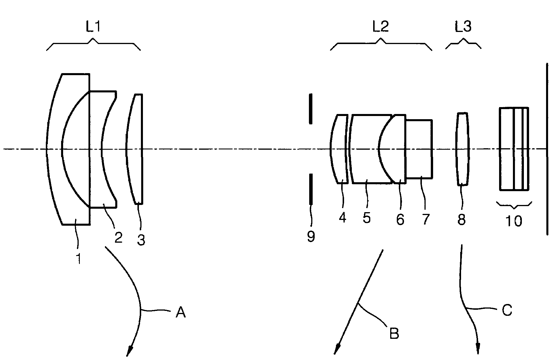
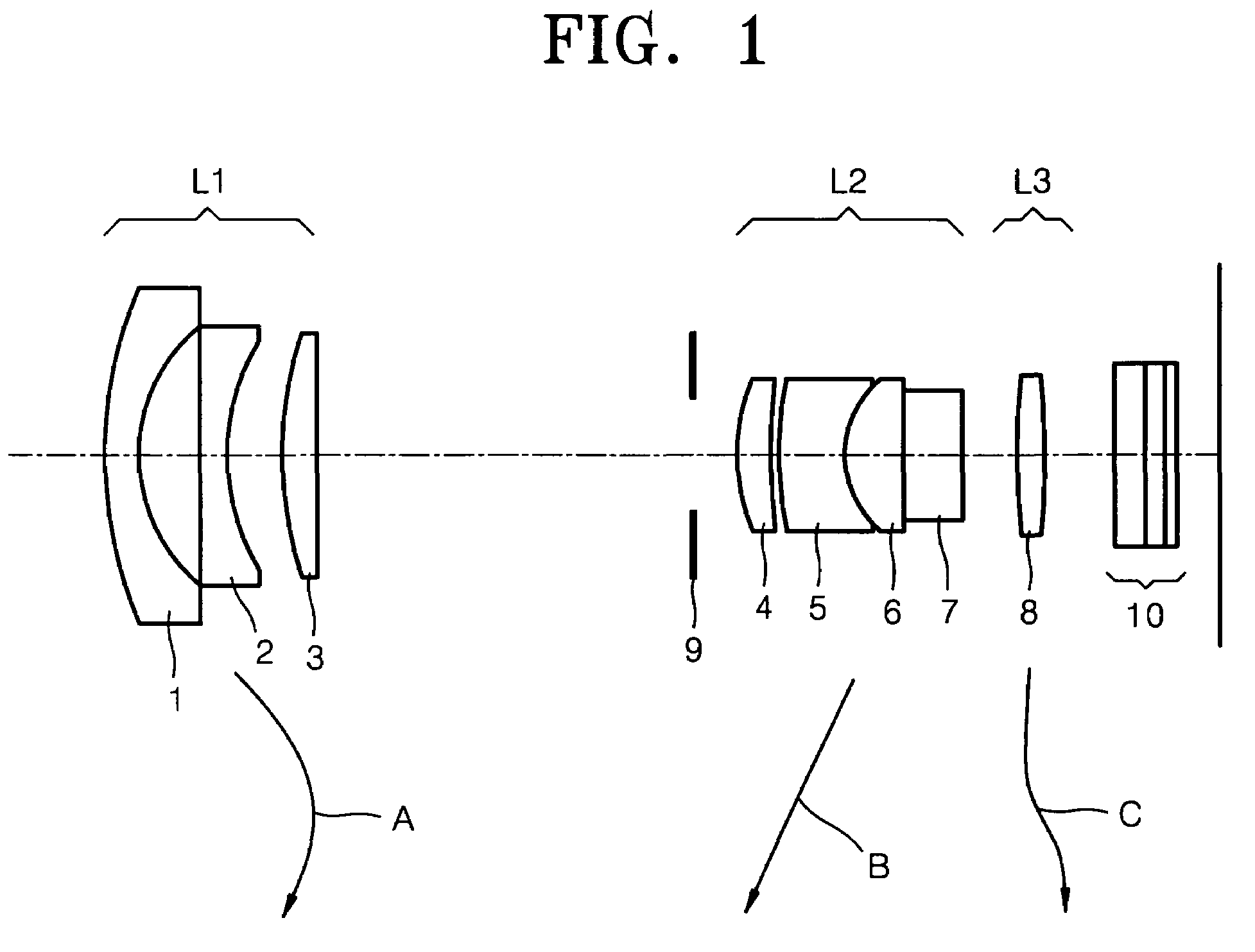
When zooming is performed from a wide angle position to a telephoto position, the second lens group L2 is moved a great distance, thereby increasing the size of the zoom lens optical system and requiring a large receiving space.
Also, since the doublet of the second lens group L2, which is used for chromatic aberration correction, is too thick, the size of the zoom lens optical system is increased even further.
In this case, it is difficult to correct spherical aberration during zooming of the optical system and achieve a zoom ratio of 2× or more.

Method used


Image

  • Compact zoom lens
  • Compact zoom lens
  • Compact zoom lens

Examples


embodiment 1

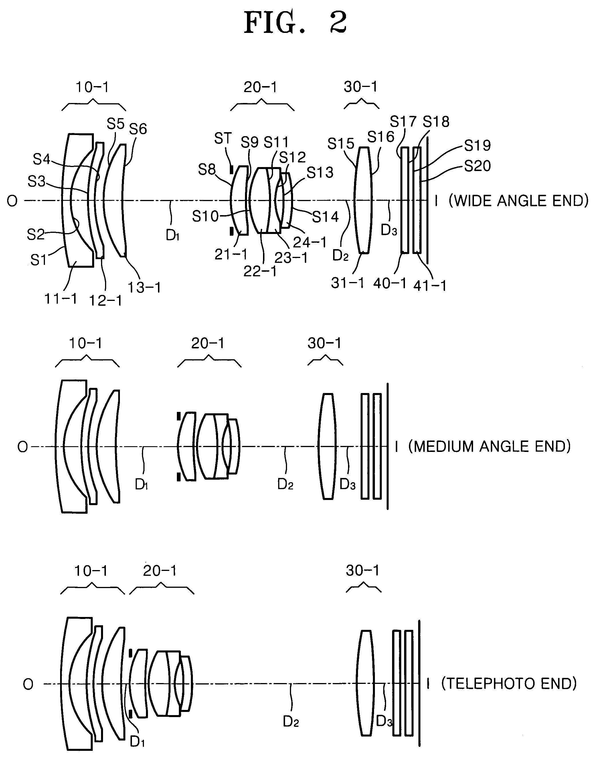
[0057]Hereinafter, f denotes a combined focal length of an entire lens system; Fno denotes an F-number; ω denotes a field angle; R denotes a radius of curvature; Dn denotes a thickness of a center of a lens or a distance between lenses; Nd denotes a refractive index; Vd denotes an Abbe number; St denotes an aperture stop; and D1, D2, and D3 denote variable distances between lenses. Reference numerals of elements in the embodiments are written with embodiment numbers.

[0058]FIG. 2 is a cross-sectional view of a zoom lens according to an embodiment of the present invention. Referring to FIG. 2, a first lens group 10-1 has a first lens 11-1, a second lens 12-1, and a third lens 13-1. A second lens group 20-1 has fourth through seventh lenses 21-1, 22-1, 23-1, and 24-1. A third lens group 30-1 has an eighth lens 31-1. Reference numeral 40-1 designates an infrared filter, and reference numeral 41-1 designates a cover glass.

[0059]

f; 6.19~10.16~17.34, Fno; 2.86~3.66~5.162, ω; 63.48~39.44~23...

embodiment 2

[0063]FIG. 5 is a cross-sectional view illustrating optical configurations of a zoom lens at a wide angle position, a medium angle position, and a telephoto position, respectively, according to another embodiment of the present invention. Referring to FIG. 5, a first lens group 10-2 has first through third lenses 11-2, 12-2, and 13-2. A second lens group 20-2 has fourth through seventh lenses 21-2, 22-2, 23-2, and 24-2. A third lens group 30-2 has an eighth lens 31-2. Reference numeral 40-2 designates an infrared filter, and reference numeral 41-2 designates a cover glass.

[0064]

f; 6.60~10.82~19.81, Fno; 3.19~4.01~6.02, 2ω; 59.82~37.18~20.43Thickness or distanceSurface(S)Radius of curvature(R)Between lenses(Dn)Refractive index(Nd)Abbe number(Vd)0:INFINITYINFINITYS1:27.3980.501.81609245.2673S2:5.3010.78S3:7.4730.501.53120056.5000(plastic lens)S4:6.3470.72ASP:K: −2.032070A: 0.408593E−03B: −.806044E−04C: −.630363E−07D: −.297865E−07S5:7.5351.081.84666323.7848S6:14.908D1ST:INFINITY0.00S8:...

embodiment 3

[0068]FIG. 8 is a cross-sectional view illustrating optical configurations of a zoom lens at a wide angle position, a medium angle position, and a telephoto position, respectively, according to still another embodiment of the present invention. Referring to FIG. 8, a first lens group 10-3 has first through third lenses 11-3, 12-3, and 13-3. A second lens group 20-3 has fourth through seventh lenses 21-3, 22-3, 23-3, and 24-3. A third lens group 30-3 has an eighth lens 31-3. Reference numeral 40-3 designates an infrared filter, and reference numeral 41-3 designates a cover glass.

[0069]

f; 6.50~10.66~19.50 Fno; 2.90~3.57~5.05 2ω; 59.38~37.22~20.70Thickness or distanceSurface(S)Radius of curvature(R)between lenses(Dn)Refractive index(Nd)Abbe number(Vd)0:INFINITYINFINITYS1:10.1131.001.82938633.1861S2:5.3862.16S3:48.4470.501.53120056.5000(plastic lens)S4:9.7750.62ASP:K: −3.001057A: 0.816584E−03B: −.116274E−04C: 0.477461E−06D: −.217586E−07S5:8.1231.211.84470623.8272S6:14.376D1ST:INFINITY0....


PUM


Abstract

A compact zoom lens that include: a first lens group having a negative refractive power; a second lens group having a positive refractive power; and a third lens group having a positive refractive power, wherein the first through third lens groups are arranged sequentially from an object when zooming is performed from a wide angle position to a telephoto position, a distance between the first lens group and the second lens group decreases and a distance between the second lens group and the third lens group increases, and the zoom lens includes at least one plastic lens and satisfies the inequality1≤(G⁢⁢1+G⁢⁢2+G⁢⁢3)fw≤1.8where G1 denotes a thickness of the first lens group, G2 denotes a thickness of the second lens group, G2 denotes a thickness of the third lens group, and fw denotes an overall focal length at the wide angle position. Accordingly, the zoom lens can ensure a high zoom ratio, and be made compact and light at low manufacturing costs.

Description

CROSS-REFERENCE TO RELATED PATENT APPLICATION[0001]This application claims the benefit of Korean Patent Application No. 10-2005-0124114, filed on Dec. 15, 2005, in the Korean Intellectual Property Office, the disclosure of which is incorporated herein in its entirety by reference.BACKGROUND OF THE INVENTION[0002]1. Field of the Invention[0003]The present invention relates to a zoom lens that can be used for an imaging optical system using a solid state imaging device and can be made compact and light at low cost.[0004]2. Description of the Related Art[0005]In general, zoom lenses used in still cameras or video cameras should have excellent optical performance, a high zoom ratio, and a compact design. Moreover, with the widespread use of electronic equipment such as portable information terminals, e.g., personal digital assistants (PDAs) or mobile terminals, digital cameras or digital video units are increasingly installed in such electronic equipment. As a result, cameras should be ...

Claims


Application Information

Patent Timeline
Patent Type & Authority Patents(United States)
IPC IPC(8): G02B15/14
CPCG02B15/177G02B15/143507G02B1/041G02B3/0062G02B3/0087G02B3/04G02B13/009G02B2003/0093
Inventor KIM, DONG-WOO
Owner SAMSUNG ELECTRONICS CO LTD
Learn More