Slider for slide fastener

a slide fastener and slider technology, applied in the direction of slide fasteners, press-button fasteners, snap fasteners, etc., can solve the problem of inability to suppress the tendency of frequency jump-up of pull-tag sliders, and achieve the effect of reducing the size and thinning of the sliders

Active Publication Date: 2007-11-13
YKK CORP
View PDF7 Cites 3 Cited by
  • Summary
  • Abstract
  • Description
  • Claims
  • Application Information

AI Technical Summary

Benefits of technology

[0012]The slider of the present invention is comprised of three members, a slider body, a pull tag and a cover member like the U.S. patent publication No. 1988761. In the slider described in the U.S. patent publication No. 1988761, the connecting portion between the slider body and the pull tag and the rotating portion between the pull tag and the cover member are joined such that the respective members are capable of moving freely. Thus, it is impossible to suppress a tendency of frequency jump-up of the pull tag.
[0028]The configuration of the accommodating concave portion can be set up appropriately depending on the configuration and size of the cover member and slider body. The cover member only has to be constructed in a simple structure and does not need to be constructed in a complicated structure. Thus, reduction in size and thinning of the slider can be achieved by setting the configuration and size of the accommodating concave portion in the cover member depending on the configuration and size of the pull tag mounting post. The effects which the present invention exerts are considerably great.

Problems solved by technology

Thus, it is impossible to suppress a tendency of frequency jump-up of the pull tag.

Method used


Image

  • Slider for slide fastener
  • Slider for slide fastener
  • Slider for slide fastener

Examples


first embodiment

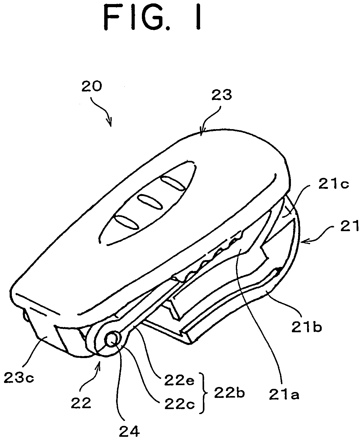
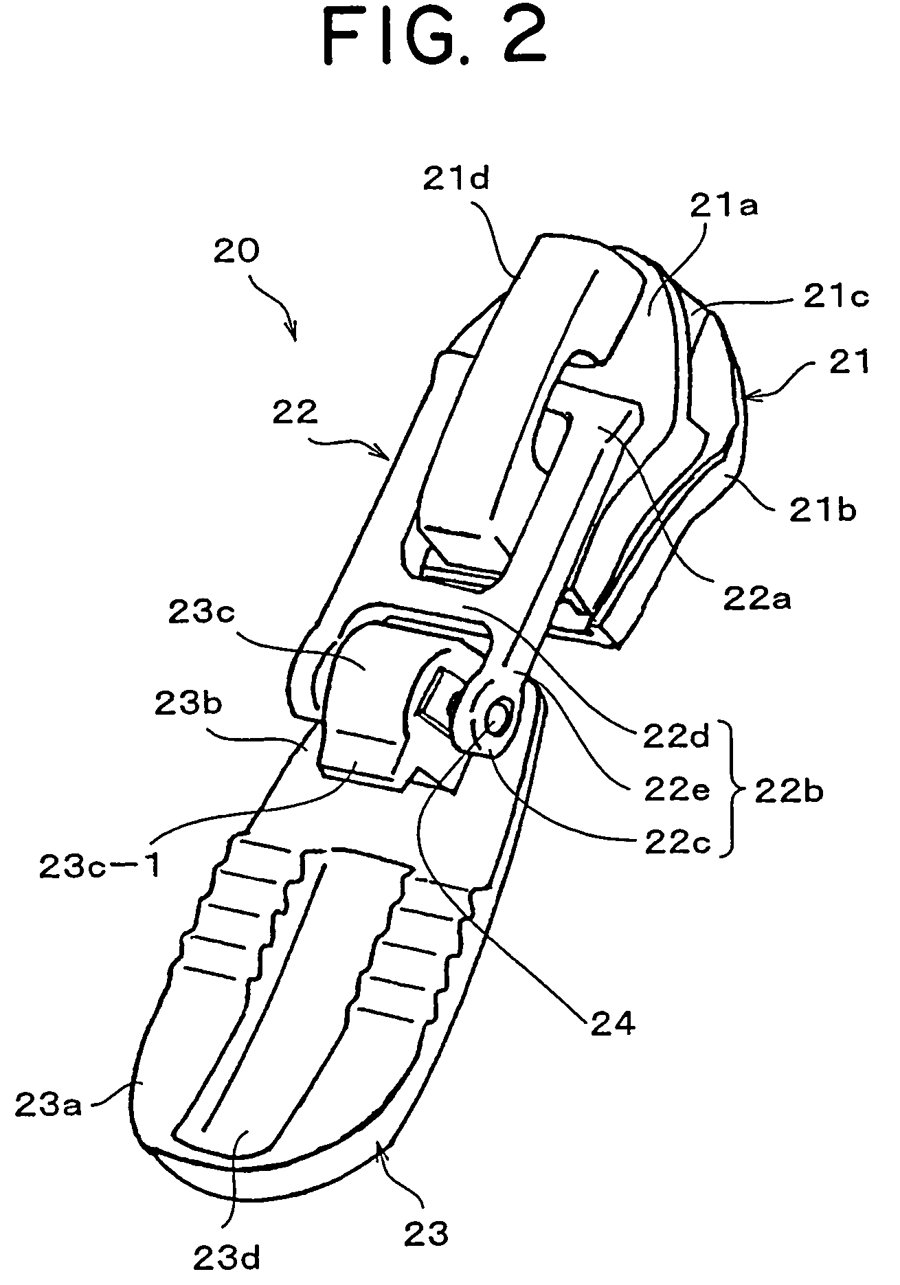
[0046]FIGS. 1 to 4 show a slider 20 having a cover member 23 according to a first embodiment of the present invention. FIG. 4 shows a slide fastener 10 comprising a pair of right and left fastener stringers 11, 12 such as, for example, a woven strap. The respective fastener stringers 11, 12 have continuous engaging elements 13, 14. This slide fastener 10 can be applied to an article such clothes (not shown), particularly to clothes which a motorcyclist wears. The respective fastener stringers 11, 12 are mounted on an opening of the article.

[0047]As shown in FIGS. 1 to 3, the slider 20 of the slide fastener 10 comprises three members, a slider body 21 which engages with / disengages from the engaging elements 13, 14 (FIG. 4), a pull tag 22 connected to the slider body 21 so as to be capable of moving freely through a first end portion 22a, and a cover member 23 having a second end portion 23b connected so as to be capable of rotating relatively through a second end portion 22b located ...

second embodiment

[0064]FIGS. 7 and 8 show another typical structure of the engaging / disengaging means for engaging with / disengaging from the second end portions 22b, 23b when the cover member 23 is located at the first position for concealing at least the pull tag 22 in the immobile state. In these figures, reference numerals are attached to substantially the same components as the first embodiment. Therefore, the detailed description of these components is omitted.

[0065]FIGS. 9 to 15 show another typical structure of the engaging / disengaging means for engaging with / disengaging from the second end portions 22b, 23b when the cover member 23 is located at the first position for concealing at least the pull tag 22 in the immobile state. Since in these embodiments, reference numerals are attached to substantially the same components as the first embodiment, the detailed description of these components is omitted.

[0066]According to the present invention, various types of engaging / disengaging means can be...

third embodiment

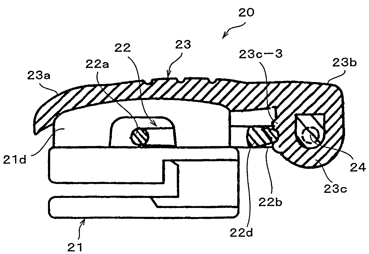
[0073]FIGS. 9 and 10 show a third embodiment of the slider 20 of the present invention. According to the third embodiment, a engaging portion, which is pressed and deformed when the pull tag 22 and the cover member 23 are engaged or disengaged, can be provided as engaging / disengaging means for engaging with / disengaging from the second end portions 22b, 23b of the pull tag 22 and the cover member 23, at a portion of the rotating portion 23c of the cover member 23 on the side of the first end portion 23a. This engaging portion can be constructed of an elastic body 23c-3 made of a soft material such as plastic or rubber.

[0074]The configuration and structure of this elastic body 23c-3 are not restricted to the indicated example. When the cover member 23 is located at the first position (FIG. 10), the elastic body 23c-3 and the joint lever 22d of the pull tag 22 made of a hard material can be disposed within the rotation space between the respective arm portions 22e in the pull tag 22 su...


PUM


Abstract

A slider for a slide fastener having a cover member capable of rotating between a first position at which a pull tag is concealed in an immobile state and a second position at which the pull tag is exposed, wherein engaging / disengaging means for engaging with / disengaging from each other when the cover member is located at the first position is provided at a portion on first end portions side apart from respective rotating portions of second end portions, the second end portion having the rotating portions in which the pull tag and the cover member are coupled so as to be able to rotate relatively, thereby providing the slider a simple structure and costing low, being capable of achieving a pull tag holding performance stable and excellent over a long period and preventing deflections between respective components.

Description

BACKGROUND OF THE INVENTION[0001]1. Field of the Invention[0002]The present invention relates to a slider for a slide fastener, and more particularly to a slider capable of achieving a pull tag holding performance stable and excellent over a long period and preventing occurrence of plays between respective components.[0003]2. Description of Related Art[0004]Conventionally, sliders have been often used as fixing devices for articles such as bag or knapsack and clothes such as jacket or sweat suit. As for the structure of this kind of slider, there is available an ordinary slider comprising a slider body made of a stiff material, which is attached to an opening of the aforementioned articles and engages with / disengages from engaging elements opposing of a pair of fastener stringers, and a pull tag made of a stiff material connected to the slider body so as to be capable of moving freely.[0005]As for another structure of the slider, there is available a slider comprising a slider body,...

Claims


Application Information

Patent Timeline
Patent Type & Authority Patents(United States)
IPC IPC(8): A44B19/26A44B19/30
CPCA44B19/301Y10T24/2561Y10T24/2586
Inventor TSENG, FA WENMATSUSHIMA, HIDEYUKIYONESHIMA, HISASHI
Owner YKK CORP
Why Eureka
Try Eureka