Zoom lens and image pickup apparatus

a technology of zoom lens and image pickup, applied in the field of zoom lens, can solve the problems of poor operability during focusing and the tendency to increase mass, and achieve the effects of suppressing the tendency, increasing mass, and reducing the tendency

Active Publication Date: 2008-02-14
FUJI PHOTO OPTICAL CO LTD
View PDF1 Cites 7 Cited by
  • Summary
  • Abstract
  • Description
  • Claims
  • Application Information

AI Technical Summary

Benefits of technology

[0025]By so doing, the lens material of the concave lens of the first group is optimized, which is advantageous to the aberration performance.
[0026]According to the zoom lens and the image pickup apparatus having the above configuration, since the respective groups in the focusing group are configured to have the positive refractive powers, and the positive refractive power is appropriately distributed among the respective groups in the focusing group. As a result, as compared with the case where the first group in the focusing group is of the negative refractive power, it is possible to suppress the tendency for the second group and the third group to increase in mass without enlarging the refractive powers of the second group and the third group more than required, to thereby make it possible to render the operability during focusing excellent.

Problems solved by technology

As a result, the thicknesses of the second group and the third group and the lens diameter tend to become large, and the mass tends to increase, so that there arises a problem that operability during focusing becomes poor.

Method used


Image

  • Zoom lens and image pickup apparatus
  • Zoom lens and image pickup apparatus
  • Zoom lens and image pickup apparatus

Examples


examples

[0100]Next, specific numerical examples of the zoom lens according to this embodiment will be described below. Hereinafter, first to fifth numerical examples will be described collectively.

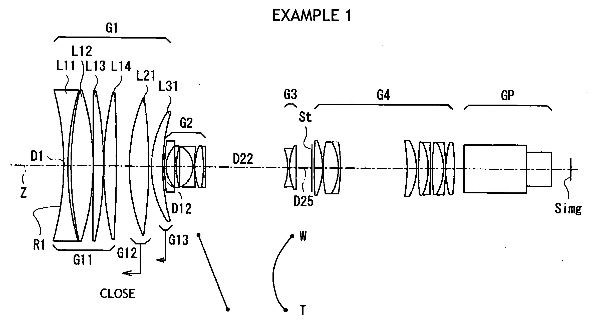
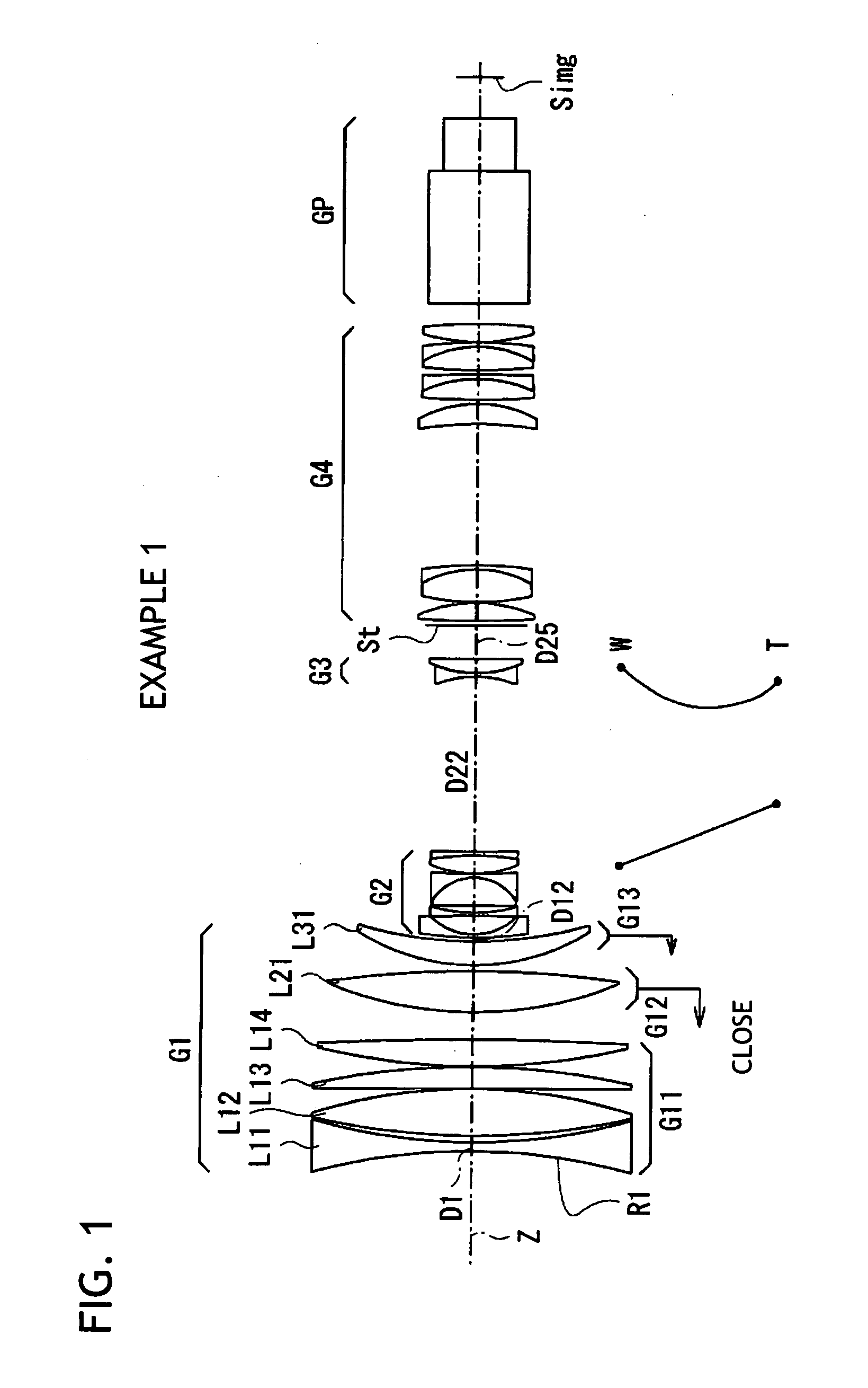
[0101]FIG. 9 shows Example 1 specific lens data corresponding to the configuration of the zoom lens shown in FIG. 1. The column for surface number Si in the lens data shown in FIG. 9 indicates the number of an i-th (i=1 to 44) surface wherein with respect to the zoom lens according to Example 1, the surface of the component element on the most subject side is referred to as a first surface, the number is sequentially incremented toward the image side. The column for a radius of curvature Ri indicates a value (mm) of the radius of curvature of the i-th surface from the object side by setting the reference character R1 attached in FIG. 1 as a radius of curvature of the first surface. Similarly, the column for a surface distance Di indicates an interval (mm) between an i-th surface Si from the object...


PUM


Abstract

A focusing group G1 is disposed on an object side relative to a variator group G2. The focusing group G1 includes, in order from the object side, a first group G11 having a positive refractive power, a second group G12 having a positive refractive power, and a third group G13 having a positive refractive power. The first group G11 has, in order from the object side, at least one concave lens (L11) and at least one convex lens. When focusing from an infinitely distant object to a close object, the second group G12 and the third group G13 are moved so that with respect to a change in an object distance, an amount of movement of the second group G12 becomes large in a region near infinity, while an amount of movement of the third group G13 becomes large in a close range.

Description

CROSS-REFERENCE TO RELATED APPLICATIONS[0001]This application is based upon and claims the benefit of priority from the Japanese Patent Application No. 2006-217945 filed on Aug. 10, 2006, the entire contents of which are incorporated herein by reference.BACKGROUND OF THE INVENTION[0002]1. Technical Field[0003]The invention relates to a zoom lens suitable for a television camera, a video camera or the like, and more particularly to a zoom lens having a focusing group closer to the object side than a variator group and adapted to focus by moving some of its lens groups, as well as an image pickup apparatus having the zoom lens.[0004]2. Description of the Related Art[0005]As a large-aperture, high zoom-ratio zoom lens suitable for a television camera or a video camera, a four-group type zoom lens has been known which includes, in order from the object side, a focusing group having a positive refractive power, a variator group having a negative refractive power, a compensation group hav...

Claims


Application Information

Patent Timeline
Patent Type & Authority Applications(United States)
IPC IPC(8): G02B15/167
CPCG02B15/173G02B15/144113
Inventor TSUTSUMI, KATSUHISATOYAMA, NOBUAKI
Owner FUJI PHOTO OPTICAL CO LTD
Why Eureka
Try Eureka