
Projection lens, and projection display and rear projection display using this projection lens

A technology of projection lens and display device, applied in the field of projection lens, can solve the problems of increased waste, inability to rationalize, and reduced aberration performance of projection lens, and achieve the effect of good aberration performance

Inactive Publication Date: 2006-11-08
PANASONIC CORP
View PDF2 Cites 15 Cited by
  • Summary
  • Abstract
  • Description
  • Claims
  • Application Information

AI Technical Summary

Problems solved by technology

As a result, in the case of offset projection, there is a problem that the resolution and brightness of the projected image are asymmetrical with respect to its screen center
In addition, only a part of the viewing angle of the effective image circle is used, so the waste increases and cannot be rationalized
Furthermore, if an offset projection is used in a rear projection display device constructed with a transmissive screen, the transmissive screen must also be offset. In terms of rationality, there is a problem that the rear projection display Device not suitable for offset projection
[0026] However, this structure hinders the rationalization of the projection system including the projection lens because the total reflection prism is very expensive.
Also, since the interior of the total reflection prism contains a minute air layer, there is a problem that the gap tolerance of the air layer causes a significant decrease in the aberration performance of the projection lens

Method used


Image

  • Projection lens, and projection display and rear projection display using this projection lens
  • Projection lens, and projection display and rear projection display using this projection lens
  • Projection lens, and projection display and rear projection display using this projection lens

Examples


reference example 1

[0109] Figure 5 It is an installation diagram showing the structure of the projection lens in Reference Example 1.

[0110] Such as Figure 5 As shown, the projection lens 13 in this reference example is composed of the following parts arranged in order from the screen 4 side to the image plane 5 side: the first lens group G1 of negative magnification, which consists of two lenses L1 as the front lens group , L2 composition; the second lens group G2 of positive magnification, which is composed of four lenses L3, L4, L5, L6 as the rear lens group; the third lens group G3 of positive magnification, which is similarly composed of the rear lens The group consists of six lenses L7, L8, L9, L10, L11, and L12; and a fourth lens group G4 of positive magnification, which is composed of a single lens L13 as an auxiliary lens group.

[0111] In addition, an aperture 14 is provided between the second lens group G2 and the third lens group G3.

[0112] In the projection lens 13 of this refer...

reference example 2

[0145] Figure 7 It is an installation diagram showing the structure of the projection lens in Reference Example 2. The projection lens 15 of this reference example is the same as the projection lens 13 of the reference example 1 in terms of the basic structure from the first lens group G1 to the fourth lens group G4 and the positional relationship between the optical axis 7 and the image plane 5.

[0146] The difference between the projection lens 15 of this reference example and the projection lens 13 of the reference example 1 is that the first projection lens group G1, the second projection lens group G2, the third projection lens group G3, and the fourth projection lens group G4 Parameters such as lens magnification distribution and surface spacing.

[0147] Represented in Table 3 below Figure 7 Specific numerical examples of each lens of the projection lens 15 are shown.

[0148] Lens

Side i

ri

di

ni

vi

L1

L2

L3

L4

L5 ...

reference example 3

[0160] Picture 9 It is an installation diagram showing the structure of the projection lens in Reference Example 3. The projection lens 16 of this reference example is the same as the projection lens 13 of the reference example 1 in terms of the basic structure from the first projection lens group G1 to the fourth lens group G4 and the positional relationship between the optical axis 7 and the image plane 5.

[0161] The difference between the projection lens 16 of this reference example and the projection lens 13 of the above-mentioned reference example 1 is the magnification distribution of the lenses constituting the first lens group G1, the second lens group G2, the third lens group G3, and the fourth lens group G4, And parameters such as surface interval.

[0162] Shown in Table 5 below Picture 9 Specific numerical examples of each lens of the projection lens 16 are shown.

[0163] Lens

Side i

ri

di

m

vi

L1

L2

L3

L4 ...


PUM


Abstract

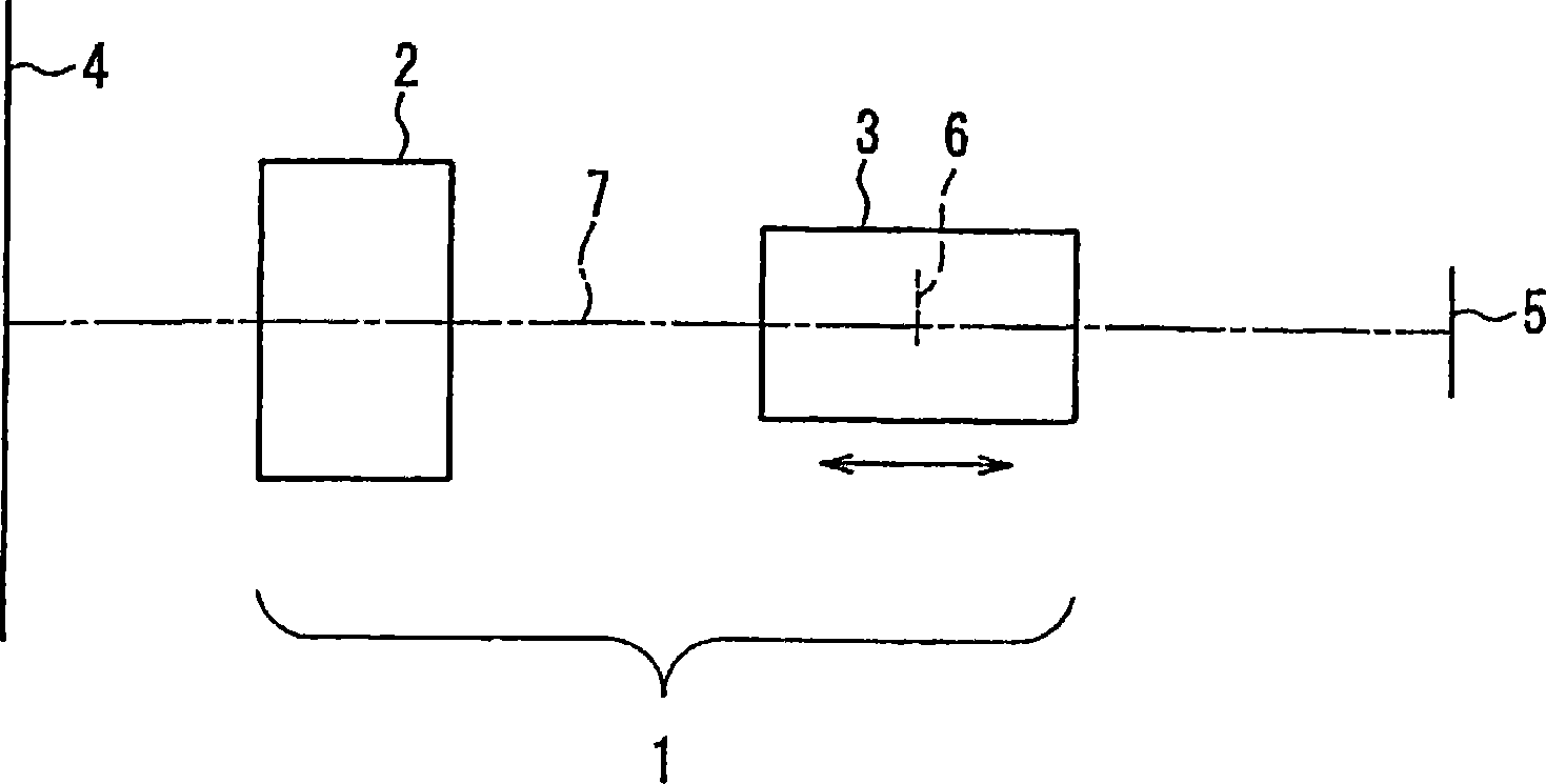
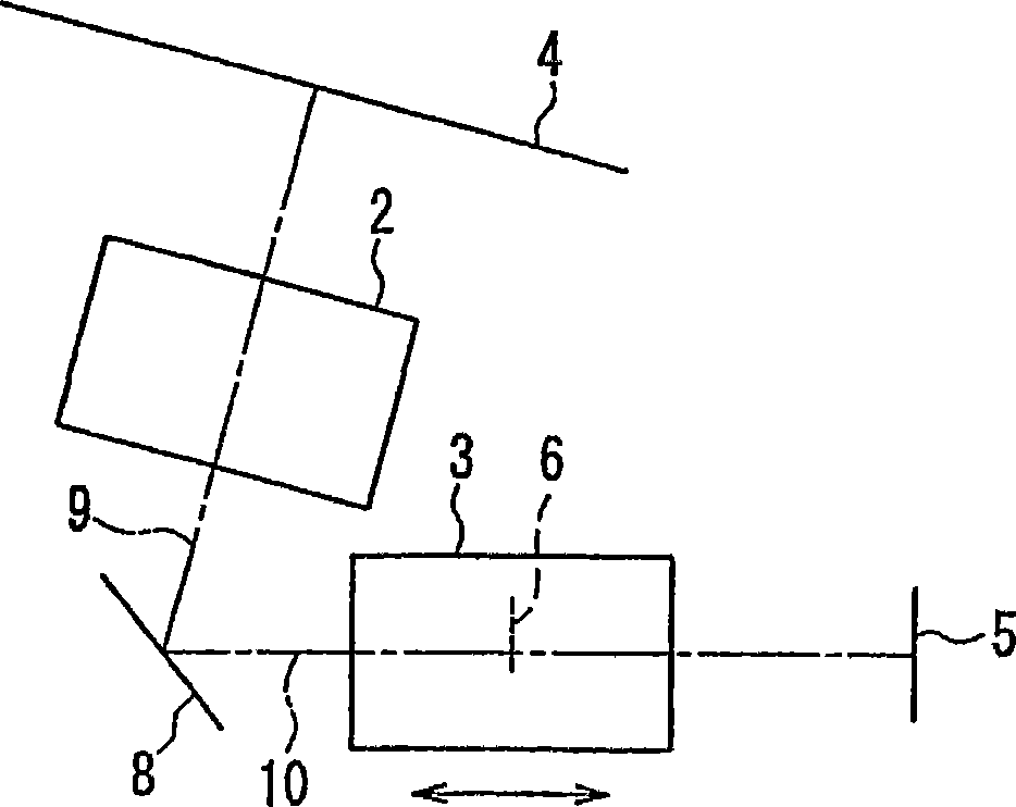
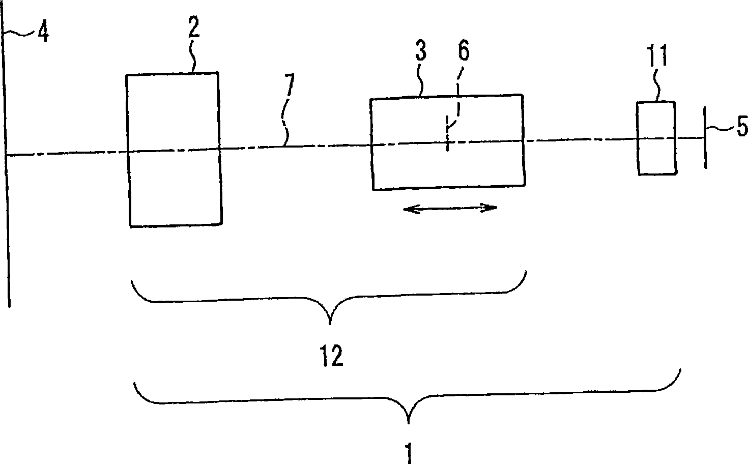
A projection lens exhibiting a good aberration performance while employing a front projection and capable of realizing the specifications required for a projection display, i.e. a low F number, a wide angle, a long back focus and a high quantity ratio of peripheral light, through a rational arrangement. The projection lens (1), for projecting an optical image formed on a spatial light modulator element (located in the vicinity of an image plane (5)) while enlarging onto a screen (4), consists of a front lens group (2) and a rear lens group (3) located sequentially from the screen (4), side toward the image plane (5) side. The rear lens group (3) is provided with a diaphragm (6) decentering from an optical axis (7) common to the front lens group (2) and the rear lens group (3). Focus is adjusted by moving the rear lens group (3) in the direction of the optical axis (7) without turning it.

Description

[0001] And back projection display device Technical field [0002] The present invention relates to a projection lens for magnifying and projecting an optical image formed on a spatial light modulation element onto a screen, and a projection display device and a rear projection display device using the projection lens. Background technique [0003] In the past, image devices for large screens have been known as projection display devices using various spatial light modulation elements. In addition, recently, a reflection type spatial light modulation element with high display efficiency such as a DMD (digital micromirror device) is attracting attention (see, for example, Japanese Patent Laid-Open No. 2000-98272). [0004] FIG. 29 shows the structure of a projection display device using DMD as a spatial light modulation element. Figure 29A A plan view is shown, and Fig. 29B is a side view. and, Figure 30 Represents a schematic diagram explaining the working principle of DMD. [0...

Claims


Application Information

Patent Timeline
Patent Type & Authority Applications(China)
IPC IPC(8): G02B13/16G02B13/04G02B13/18H04N9/31
CPCG02B13/04G02B13/16H04N9/3114H04N9/3147
Inventor 和田充弘
Owner PANASONIC CORP
Learn More