
Device for actuating a gas exchange valve

a technology for gas exchange valves and actuators, which is applied in the direction of non-mechanical valves, electrical control, machines/engines, etc., can solve the problems of armature not bearing with constant closing, destroying the valve seats, and unable to fully support the armature against the pol

Inactive Publication Date: 2002-02-14
DAIMLER AG
View PDF0 Cites 0 Cited by
  • Summary
  • Abstract
  • Description
  • Claims
  • Application Information

AI Technical Summary

Benefits of technology

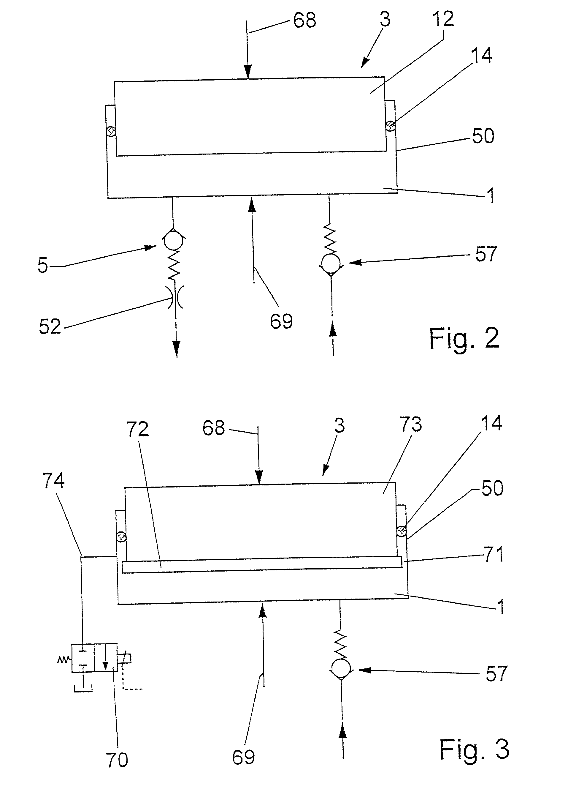
[0015] With the gas exchange actuating device according to the invention, the compensating element maintains its setting when the internal combustion engine is at a standstill. This can be brought about by the compensating element being blocked mechanically, electrically or hydraulically when the internal combustion engine is shut down. one simple option is for the discharging of the pressurized fluid via the leakage area to be controllable by means of a valve. The valve can be a solenoid valve which, in the deenergized state, blocks the flow through the leakage area. The said valve can be activated as a function of suitable operating parameters of the internal combustion engine, so that discharging from the pressure space is possible only at certain time slots of the actuating cycle of the gas exchange valve. Otherwise, the effect is achieved by the compensating element being blocked hydraulically when the internal combustion engine is at a standstill, thereby maintaining its setting.
[0017] A particular embodiment of the invention is based on the recognition that, in the case of devices for actuating gas exchange valves, the force acting on a compensating element during the working cycles fluctuates cyclically between a maximum and a minimum value, because of mass forces of inertia, pressure fluctuations in the cylinder head and, in particular in the case of devices which have at least one valve spring acting on the gas exchange valve, because of the change in the tension force over a working period. These fluctuations, which occur only during the working cycles, are used by the invention to achieve a defined leakage rate during the working cycles and to suppress the tendency for the compensating element to become slowly shorter or, in particular arrangements, to become longer when the internal combustion engine is at a standstill. During an engine shutdown, the compensating element therefore maintains its setting essentially unchanged.

Problems solved by technology

Furthermore, variables of this type and wear on the valve seats may lead to the armature not bearing with a constant closing force against the pole face of the closing magnet or already bearing against it before the gas exchange valve is completely closed.
Hot combustion gases, which escape past valves that are not tightly closed, destroy the valve seats.
Also, different thermal expansions may cause the armature to no longer bear completely against the pole face of the closing magnet when the gas exchange valve is closed.
As a result, the energy requirement of the closing magnet sharply increases.
Furthermore, this process is generally associated with a reduced opening stroke of the gas exchange valve, with the result that the throttling losses increase during the charge cycle and the efficiency deteriorates.
This process may last for a number of working cycles of the gas exchange valve and may, in particular, lead to noises, unnecessary wear and to an additional expenditure of energy.
However, should pumping up, i.e. a continuous expansion of the second play-adjusting element, take place during the valve operation because of resonant oscillations or an excessively high lubricating oil pressure, etc., the positive control via the closing cam would enable impermissibly high valve forces or pressures to occur which can be dissipated, in the case of the proposed design, by opening the pressure relief valve.

Method used


Image

  • Device for actuating a gas exchange valve
  • Device for actuating a gas exchange valve
  • Device for actuating a gas exchange valve

Examples


Embodiment Construction

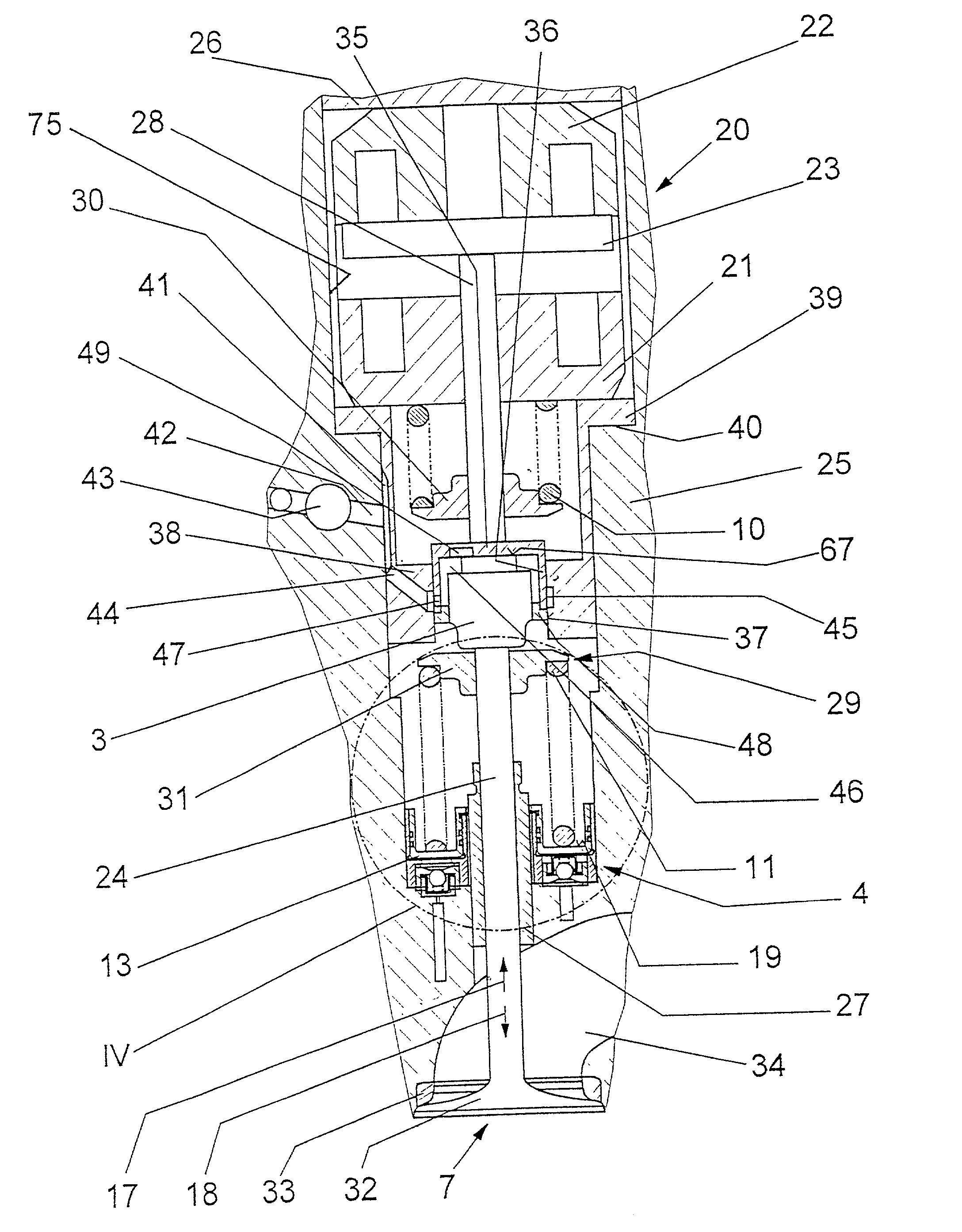
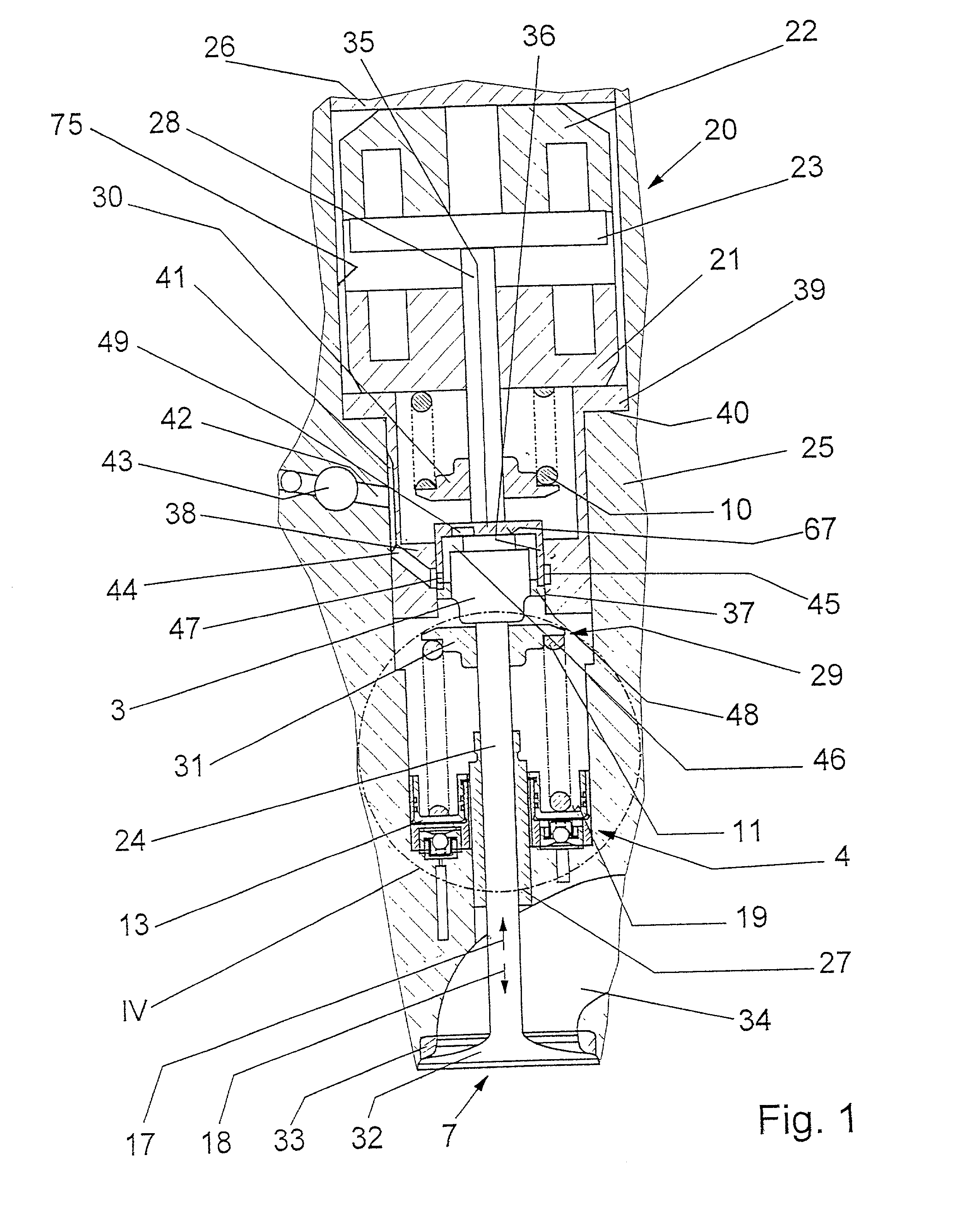
[0028] An electromagnetic actuator 20 is embedded in a recess 75 in a cylinder head 25, which recess is closed by a cylinder-head, cover 26 (not illustrated in further detail). The actuator 20 operates a gas exchange valve 7, which is guided by its valve stem 24 in the cylinder head 25 by means of a valve-stem guide 27. The actuator 20 has two operating magnets, specifically an upper closing magnet 22 and a lower opening magnet 21. An armature 23, which acts on the valve stem 24 of the gas exchange valve 7 via an armature tappet 28, moves between the pole faces of the operating magnets 21 and 22.

[0029] A spring housing 29, in which a spring mechanism comprising two valve springs 10 and 11 is accommodated, is provided between the opening magnet 21 and the gas exchange valve 7.

[0030] The upper valve spring 10 acts with one end in the valve opening direction 18 on a spring disc 30, which is movable by the gas exchange valve 7, and is supported at the other end by the opening magnet 21....


PUM


Abstract

In a device for actuating a gas exchange valve for internal combustion engines, having at least one compensating element which is arranged in the force path of an actuating element of the gas exchange valve and which has a pressure space which is formed by a piston and a working cylinder and is connected to a pressurized fluid supply space via a non-return valve and a throttling portion, via which pressure fluid can be discharged from the pressure space during the working cycles. The pressure space is sealed to the outside, and the compensating element includes a high-pressure valve, via which pressure medium can be discharged in a throttled manner during the working cycles of the gas exchange valve as the high-pressure valve opens at a predetermined force on the compensating element and closes at a predetermined force which is greater than an average force and smaller or equal to a maximum force on the compensating element.

Description

[0001] This is a Continuation-In-Part application of International Application PCT / EP00 / 00156 filed Jan. 12, 2000 and claiming the priorities of German patent applications 199 60 951.1 filed Jan. 13, 2000 and 199 56 136.2 filed Nov. 23, 1999.[0002] The invention relates to a device for actuating a gas exchange of an internal combustion engine including a hydraulic compensating structure.[0003] Electromagnetic actuators for actuating the gas exchange valves generally have two operating magnets--one opening magnet and one closing magnet between whose pole faces an armature is arranged such that it can be displaced coaxially with the valve axis. The armature acts on a valve stem of the gas exchange valve either directly or via an armature tappet. In the case of actuators according to the principle of the mass oscillator, a prestressed spring mechanism acts on the armature. Usually, two prestressed valve springs, an upper valve spring of which biases the gas exchange valve in the openin...

Claims


Application Information

Patent Timeline
Patent Type & Authority Applications(United States)
IPC IPC(8): F01L1/24F01L9/20F02D13/02F02D45/00
CPCF01L1/24F01L9/04F01L9/20
Inventor KREITMANN, FRITZMULLER, HAGENGAISBERG, ALEXANDER VON
Owner DAIMLER AG
Learn More