
Telescopically adjustable pipe

a telescoping and adjustable technology, applied in the field of telescoping, can solve the problems of inconvenient operation for users of conventional telescoping adjustable pipes, and achieve the effect of easy and rapid adjustment of length

Inactive Publication Date: 2007-11-13
HO CHENG GARDEN TOOLS
View PDF11 Cites 98 Cited by
  • Summary
  • Abstract
  • Description
  • Claims
  • Application Information

AI Technical Summary

Benefits of technology

[0006]The primary objective of the present invention is to provide a telescopically adjustable pipe whose length can be adjusted easily and rapidly.
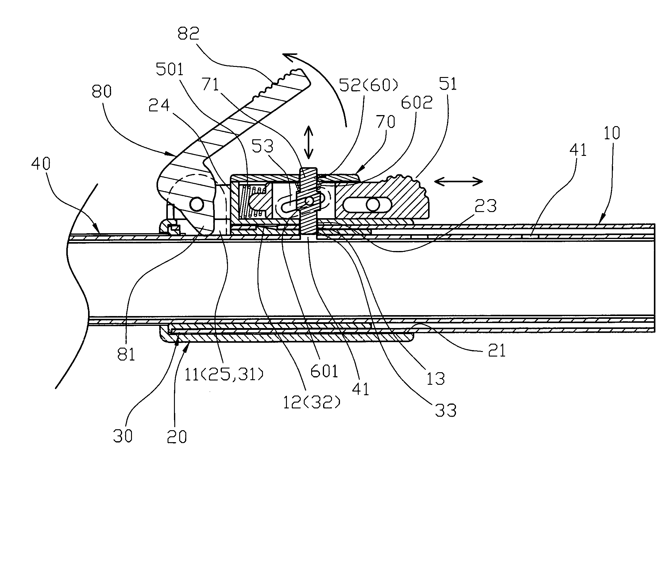
[0007]Another objective of the present invention is to provide a telescopically adjustable pipe, wherein the positioning member is locked in the respective positioning hole of the inner tube to lock the inner tube in the outer tube, so that the inner tube is locked in and cannot slip from the outer tube.
[0009]A further objective of the present invention is to provide a telescopically adjustable pipe, wherein the push member and the positioning member are pushed to return to the original position by the restoring force of the elastic member and the elastic member respectively, so that the positioning member is locked in the respective positioning hole of the inner tube so as to lock the inner tube in the outer tube automatically, thereby facilitating a user adjusting the length of the telescopically adjustable pipe.

Problems solved by technology

However, the inner tube is clamped in the outer tube by friction between the inner tube is fitted in the outer tube, so that the inner tube is not positioned in the outer tube closely and easily slips from the outer, thereby causing inconvenience to a user in operation of the conventional telescopically adjustable pipe.

Method used


Image

  • Telescopically adjustable pipe
  • Telescopically adjustable pipe
  • Telescopically adjustable pipe

Examples


Embodiment Construction

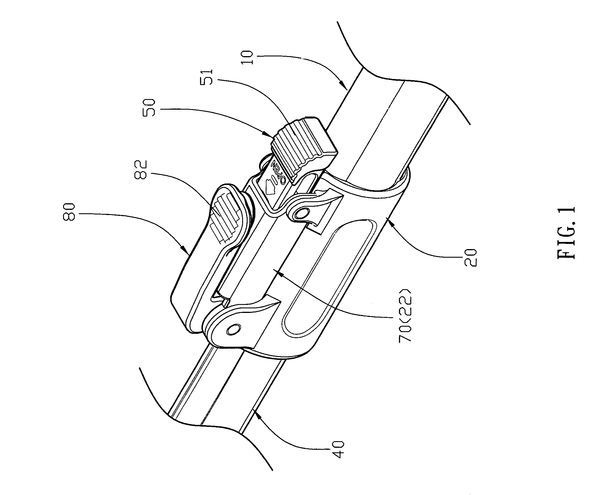
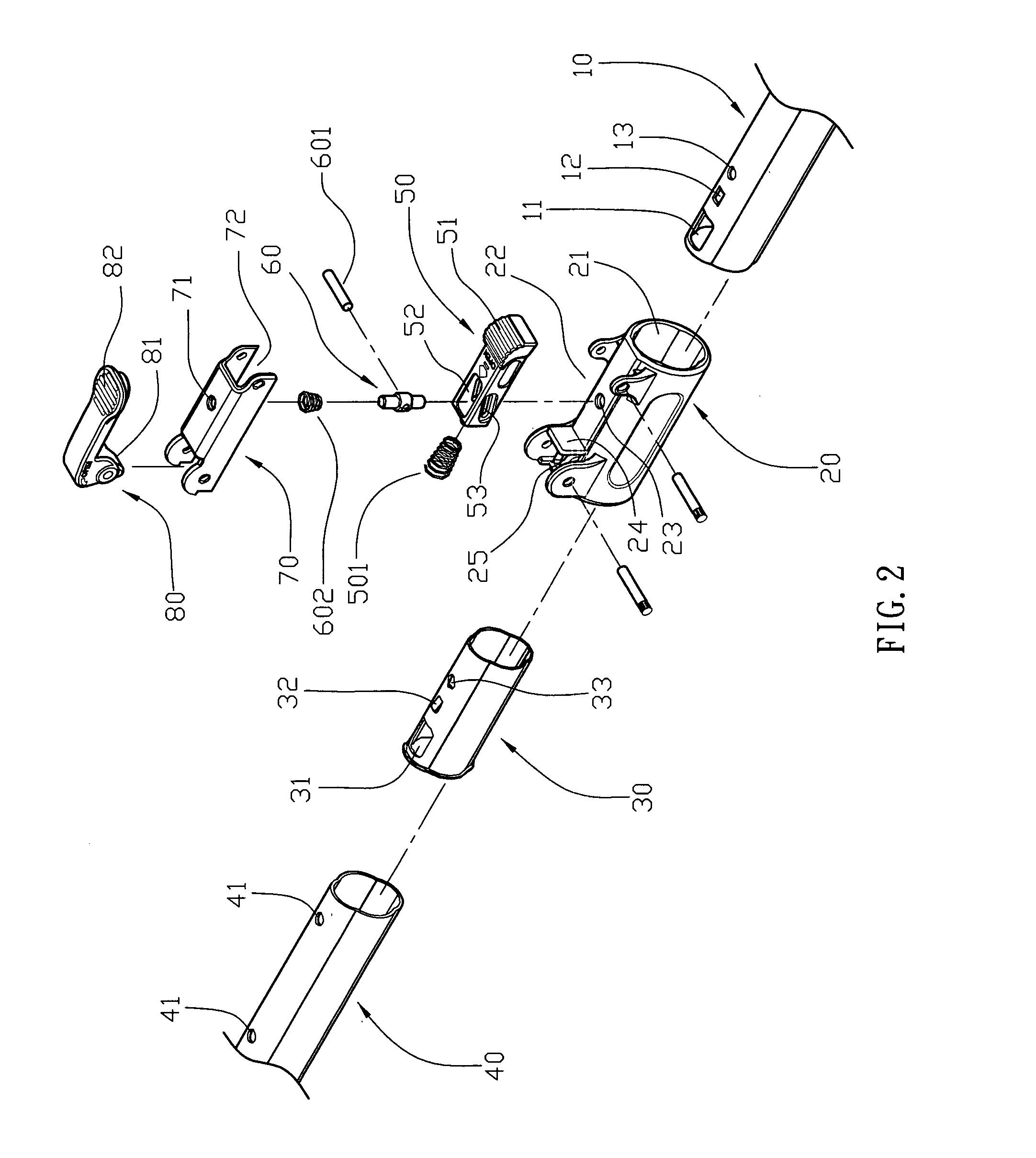
[0015]Referring to the drawings and initially to FIGS. 1-3, a telescopically adjustable pipe in accordance with the preferred embodiment of the present invention comprises an outer tube 10, an inner tube 40, an inner bushing 30, a sleeve 20, a push member 50, a mounting bracket 70, a positioning member 60, and a retaining member 80.

[0016]The outer tube 10 has an end portion formed with a through hole 13, a locking hole 12 and an opening 11.

[0017]The inner tube 40 is movably mounted in the outer tube 10 and has an end portion formed with a plurality of positioning holes 41.

[0018]The inner bushing 30 is mounted between the end portion of the outer tube 10 and the end portion of the inner tube 40 and has a peripheral wall formed with a through hole 33 aligning with the through hole 13 of the outer tube 10, a wedge-shaped locking block 32 locked in the locking hole 12 of the outer tube 10 and an opening 31 aligning with the opening 11 of the outer tube 10.

[0019]The sleeve 20 is mounted ...


PUM


Abstract

A telescopically adjustable pipe includes an outer tube, an inner tube, an inner bushing, a sleeve, a push member, a mounting bracket, a positioning member, and a retaining member. Thus, the positioning member is moved by movement of the push member and is detachably locked in the respective positioning hole of the inner tube to lock the inner tube in the outer tube, so that the inner tube is locked in and cannot slip from the outer tube.

Description

BACKGROUND OF THE INVENTION[0001]1. Field of the Invention[0002]The present invention relates to a telescopically adjustable pipe, and more particularly to a telescopically adjustable pipe for a gardening tool, such as a pair of long-arm pruning shears or the like.[0003]2. Description of the Related Art[0004]A conventional telescopically adjustable pipe for a gardening tool, such as a pair of long-arm pruning shears or the like, comprises an outer tube and an inner tube retractably mounted in the outer tube. However, the inner tube is clamped in the outer tube by friction between the inner tube is fitted in the outer tube, so that the inner tube is not positioned in the outer tube closely and easily slips from the outer, thereby causing inconvenience to a user in operation of the conventional telescopically adjustable pipe.SUMMARY OF THE INVENTION[0005]In accordance with the present invention, there is provided a telescopically adjustable pipe, comprising an outer tube; an inner tub...

Claims


Application Information

Patent Timeline
Patent Type & Authority Patents(United States)
IPC IPC(8): F16B7/10F16B21/00
CPCF16B7/105Y10T403/595Y10T403/7088Y10T403/32475Y10T403/599Y10T403/32467Y10T403/32483
Inventor HUANG, YAO-CHUNG
Owner HO CHENG GARDEN TOOLS
Learn More