Methods and systems for identifying high-quality phase angle measurements in an interferometric radar system

a technology of interferometry and phase angle, applied in the field of radar systems, can solve the problems of adding latency to the radar altimeter system and not taking advantage of information availabl

Active Publication Date: 2007-11-13
HONEYWELL INT INC
View PDF18 Cites 19 Cited by
  • Summary
  • Abstract
  • Description
  • Claims
  • Application Information

AI Technical Summary

Problems solved by technology

However, such filtering adds latency to the radar altimeter system, and does not take advantage of information available in the original signal.

Method used


Image

  • Methods and systems for identifying high-quality phase angle measurements in an interferometric radar system
  • Methods and systems for identifying high-quality phase angle measurements in an interferometric radar system
  • Methods and systems for identifying high-quality phase angle measurements in an interferometric radar system

Examples


Embodiment Construction

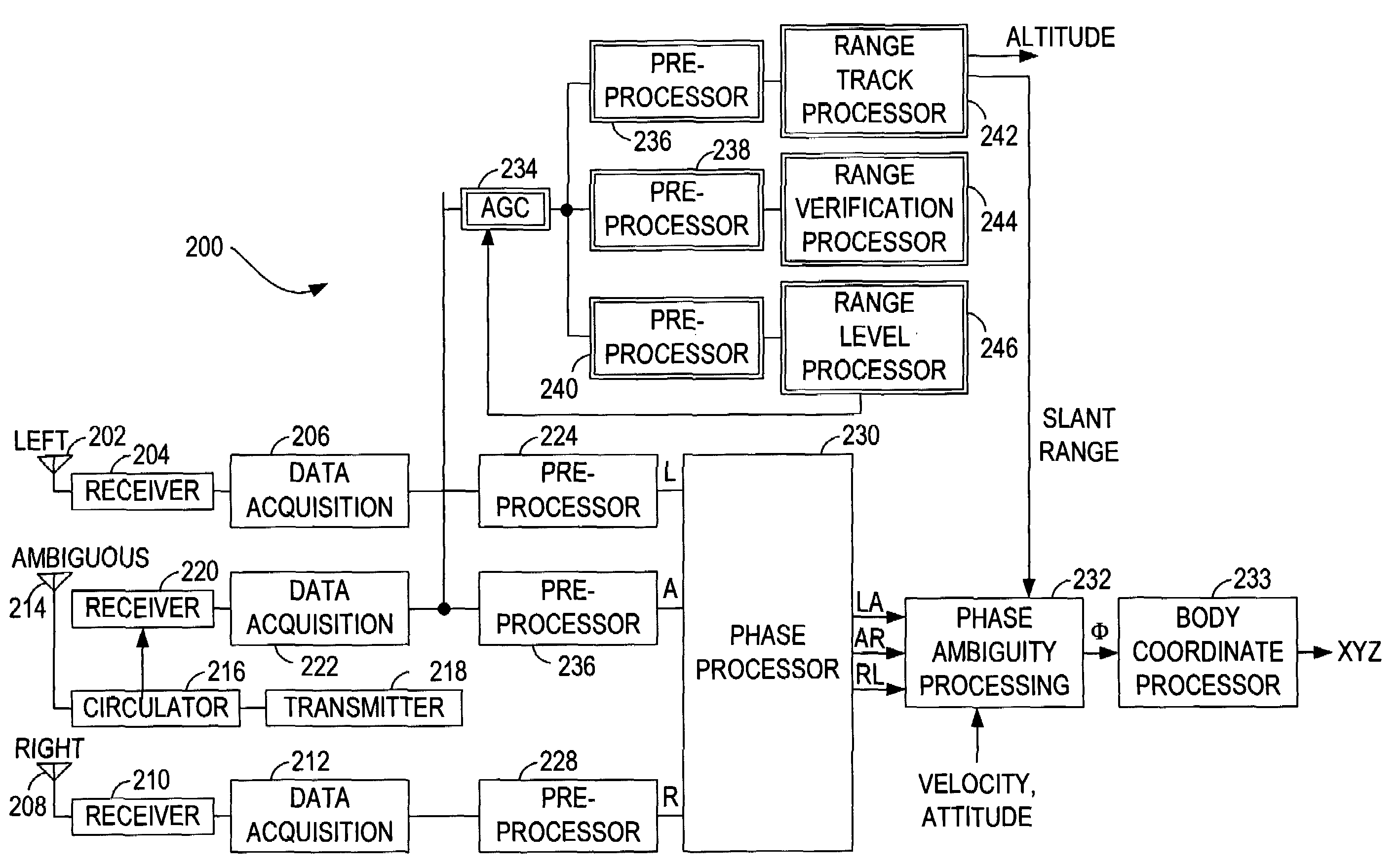
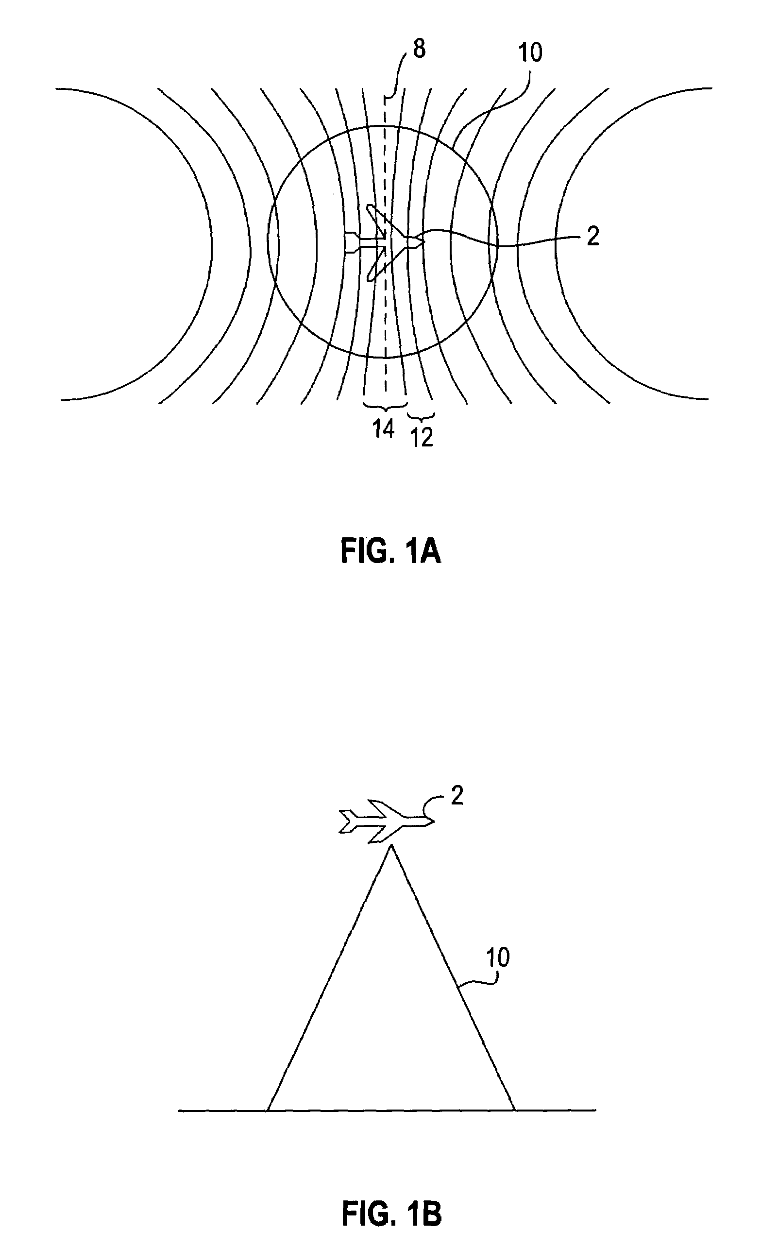
[0022]FIG. 1 shows an aircraft 2 with the Doppler effect illustrated by isodops as a result of selection by the use of Doppler filters. For ease of description aircraft 2 is assumed to have a vertical velocity of zero. As is known, if a vertical velocity exists, the median 8 of the Doppler effect will shift depending on the vertical velocity. If the aircraft 2 has a vertical velocity in a downward direction, the median of the Doppler would shift to the right of the figure. If the aircraft 2 has a vertical velocity in an upward direction, the Doppler would shift to the left of the figure.

[0023]There is herein described a combination Doppler radar / interferometer to navigate an aircraft 2 with respect to terrain features below aircraft 2. As used herein, aircraft is used to identify all flight platforms which may incorporate a radar system, including, but not limited to, jets, airplanes, unmanned aerial vehicles, missiles, and guided weapons. The radar also functions with an electronic...


PUM


Abstract

A method for determining a mechanical angle to a radar target utilizing a multiple antenna radar altimeter is described. The method comprises receiving radar return signals at the multiple antennas, populating an ambiguity resolution matrix with the electrical phase angle computations, selecting a mechanical angle from the ambiguity resolution matrix that results in a least amount of variance from the electrical phase angle computations, and using at least one other variance calculation to determine a quality associated with the selected mechanical angle.

Description

STATEMENT REGARDING FEDERALLY SPONSORED RESEARCH & DEVELOPMENT[0001]The United States Government has acquired certain rights in this invention pursuant to Contract No. N00019-01-C-0033 issued by the Department of the Navy.BACKGROUND OF THE INVENTION[0002]This invention relates generally to radar systems, and more specifically to a radar system which is capable of determining the phase angle of radar return signals.[0003]The proper navigation of an aircraft in all phases of its flight is based to a large extent upon the ability to determine the terrain and position over which the aircraft is passing. Pulse radar altimeters accurately determine altitude using leading edge return signal tracking. Specifically, a pulse radar altimeter transmits a pulse of radio frequency (RF) energy, and a return echo is received and tracked using a tracking system. The interval of time between signal bursts of a radar system is referred to as a pulse repetition interval (PRI). The frequency of bursts i...

Claims


Application Information

Patent Timeline
Patent Type & Authority Patents(United States)
IPC IPC(8): G01S13/08G01S7/40
CPCG01S3/48G01S7/292G01S13/94G01S13/882G01S13/18G01S13/935
Inventor BURLET, TODD R.KUDE, TIKA M.OVEN, JAMES B.REILLY, TIMOTHY J.
Owner HONEYWELL INT INC
Why Eureka
Try Eureka