System and method for mapping object-oriented program code to a database layer
a database and object-oriented technology, applied in the field of data processing systems, can solve the problems of not having a standard mechanism for specifying the relationship between various cmp fields and relationships, and no standard mechanism exists for generating a database schema
Active Publication Date: 2007-11-13
SAP AG
View PDF23 Cites 47 Cited by
- Summary
- Abstract
- Description
- Claims
- Application Information
AI Technical Summary
Benefits of technology
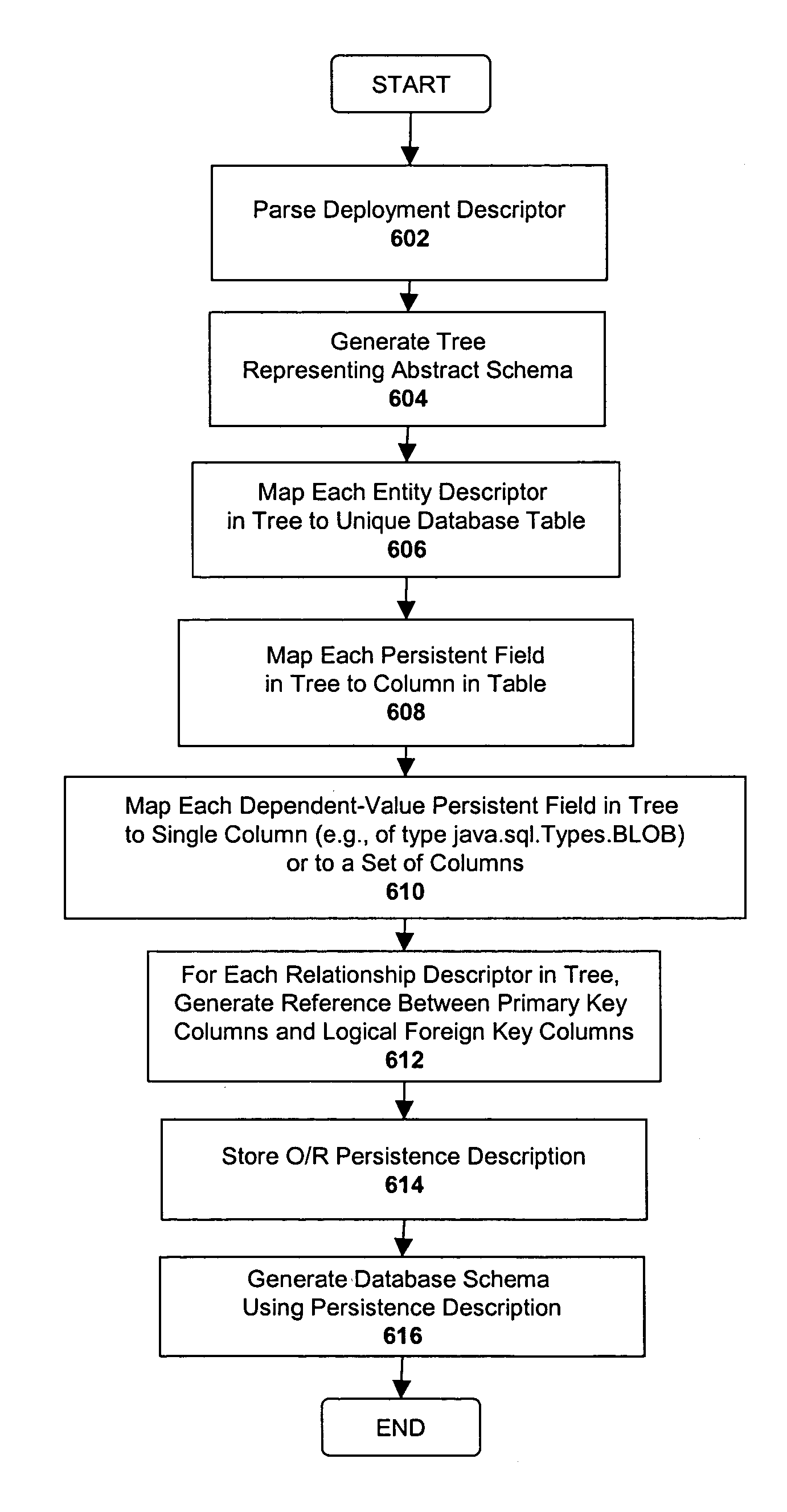
[0018]One embodiment of the invention employs techniques for providing a verification of an object-relational (“O/R”) mapping between persistent data objects (i.e., the objects that represent persistent data) and relational database objects. In one embodiment, Each entity bean is mapped to a particular database table, and each of the persistent fields within the entity bean are mapped to columns of the da
Problems solved by technology
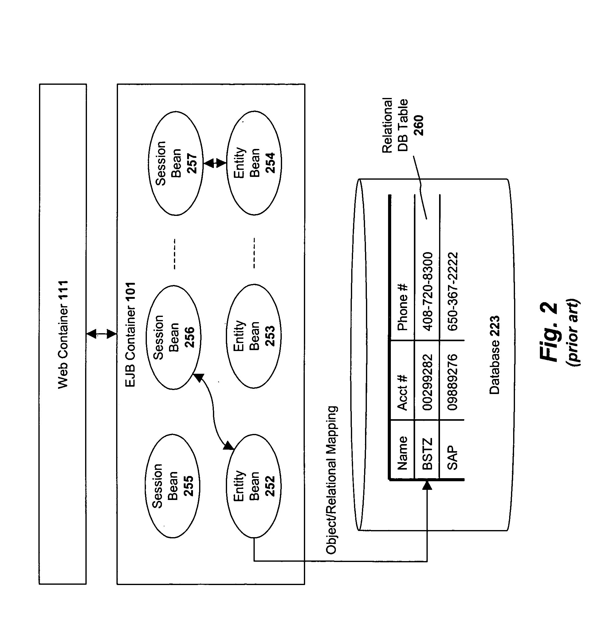
However, no standard mechanism exists for specifying how the various CMP fields and relationships are mapped to relational database tables.
In addition, no standard mechanisms exist for generating a database schema which matches the object schema of an existing object-oriented application.
Method used
View moreImage
Smart ImageViewing Examples
Examples
example
[0207][0208][0209]myHelpTable[0210][0211]myReferencingBean[0212]myCmrField[0213]myFKColumn[0214][0215][0216]myReferencedBean[0217]myOtherCmrField[0218]myOtherFKColumn[0219][0220]
[0221][0222]AEJB_BEJB—2[0223][0224]AEJB[0225]b[0226][0227]id—0—0—2[0228]id[0229][0230][0231][0232]BEJB[0233]a[0234][0235]id—0—1—2[0236]id[0237][0238]
[0239]
[0240][0241][0242]BeanEJB[0243]a1[0244][0245]id——0—0[0246]id[0247][0248][0249][0250]AEJB[0251][0252]
[0253]
-->
Login to View More PUM
 Abstract
One embodiment of the invention employs techniques for providing a default object-relational mapping between persistent data objects (i.e., the objects that represent persistent data from a database) and a relational database. In a Java environment, for example, each entity bean is mapped to a particular database table, and each of the persistent fields within the entity bean are mapped to columns of the database table. Relationships between entity beans are expressed as mappings between primary keys and foreign keys within the database schema. Dependent-value persistent fields may be mapped to multiple columns or to a single column of a special Java type (java.sql.Types. BLOB). In addition, one embodiment of the invention generates a default database schema using the default O / R mapping by executing a series of SQL commands generating the tables and columns.
Description
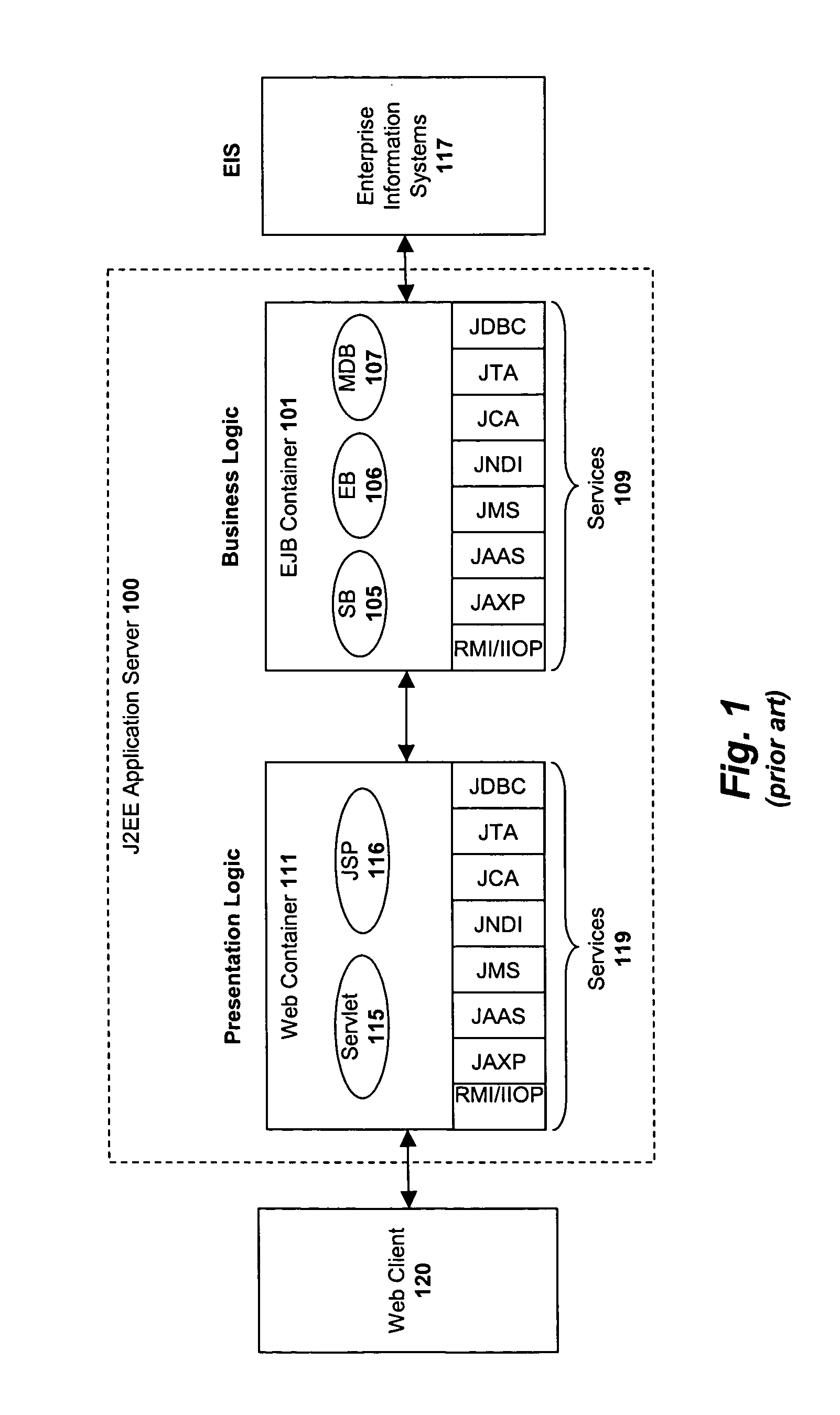
BACKGROUND[0001]1. Field of the Invention[0002]This invention relates generally to the field of data processing systems. More particularly, the invention relates to a system and method for mapping objects within an object-oriented environment to a database schema and for automatically generating a database schema.[0003]2. Description of the Related ArtMulti-Tier Enterprise Computing Systems[0004]Java 2 Enterprise Edition (“J2EE”) is a specification for building and deploying distributed enterprise applications. Unlike traditional client-server systems, J2EE is based on a multi-tiered architecture in which server side program code is divided into several layers including a “presentation” layer and a “business logic” layer.[0005]FIG. 1 illustrates an exemplary J2EE application server 100 in which the presentation layer is implemented as a Web container 111 and the business layer is implemented as an Enterprise Java Bean (“EJB”) container 101. Containers are runtime environments which ...
Claims
Login to View More Application Information
Patent Timeline
 IPC IPC(8): G06F17/30
CPCG06F8/74Y10S707/99944Y10S707/99943
Inventor IVANOVA, VIKTORIYA TS
Owner SAP AG
Features
- R&D
- Intellectual Property
- Life Sciences
- Materials
- Tech Scout
- Unparalleled Data Quality
- Higher Quality Content
- 60% Fewer Hallucinations
Learn More Browse by: Latest US Patents, China's latest patents, Technical Efficacy Thesaurus, Application Domain, Technology Topic, Popular Technical Reports.
© 2025 PatSnap. All rights reserved.Legal|Privacy policy|Modern Slavery Act Transparency Statement|Sitemap|About US| Contact US: help@patsnap.com


