Heat exchanger apparatus incorporating elliptically-shaped serpentine tube bodies

a technology of heat exchanger and serpentine tube body, which is applied in the direction of lighting and heating apparatus, tubular elements, stationary conduit assemblies, etc., and can solve problems such as greater corrosion

Active Publication Date: 2007-11-20
EVAPCO
View PDF4 Cites 33 Cited by
  • Summary
  • Abstract
  • Description
  • Claims
  • Application Information

AI Technical Summary

Problems solved by technology

Such surface-to-surface contact slightly reduces heat exchange capacity of the heat exchanger incorporating this structure and might result in corrosion at a level greater than point contact between contacting return bends.

Method used


Image

  • Heat exchanger apparatus incorporating elliptically-shaped serpentine tube bodies
  • Heat exchanger apparatus incorporating elliptically-shaped serpentine tube bodies
  • Heat exchanger apparatus incorporating elliptically-shaped serpentine tube bodies

Examples


Embodiment Construction

[0032]Hereinafter, the exemplary embodiment of the present invention will be described with reference to the attached drawings.

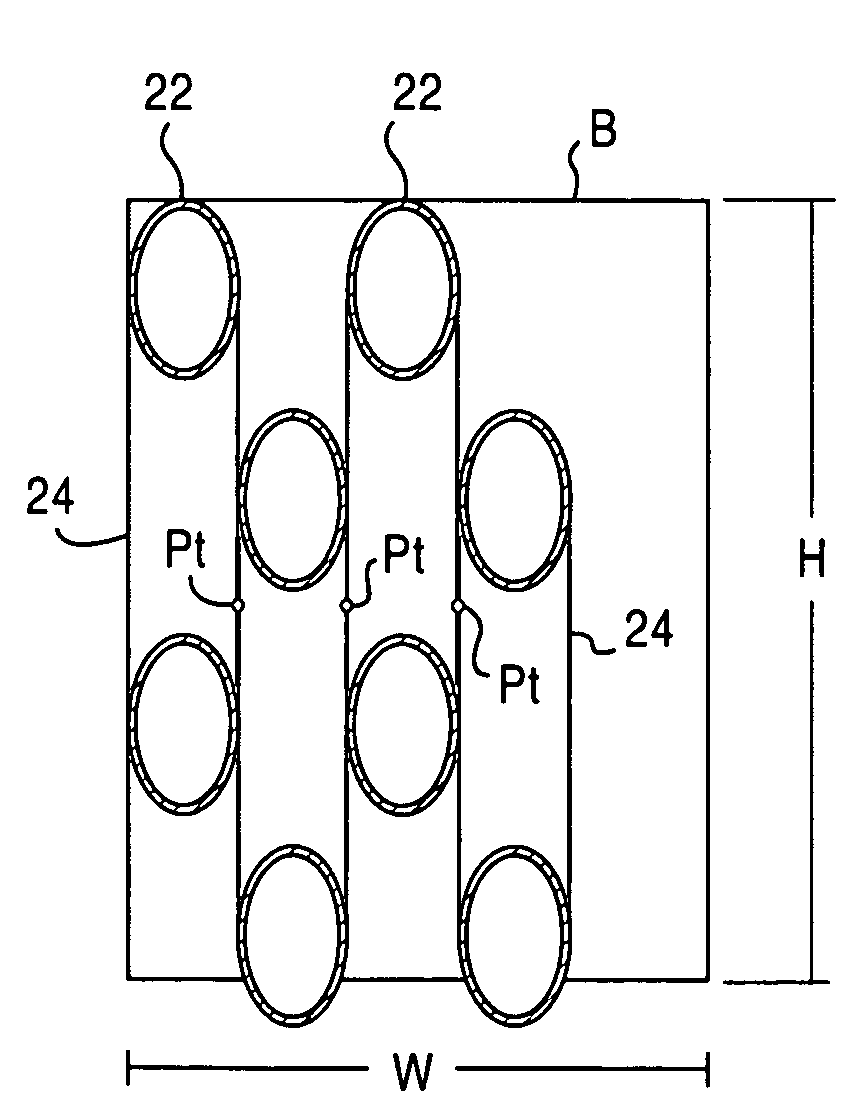
[0033]An exemplary embodiment of a heat exchanger apparatus 10 of the present invention is hereinafter described with reference to FIGS. 7-16. With reference to FIG. 7, the heat exchanger apparatus 10 of the present invention includes an inlet header 12, an inlet connection 14 connected to the inlet header 12, an outlet header 16, an outlet connection 18 connected to the outlet header 16 and a plurality of serpentine tube bodies 20. The plurality of serpentine tube bodies 20 interconnect and are in communication with the inlet header 12 and outlet header 16. With reference to FIGS. 8-13, each serpentine tube body 20 has a plurality of straight tube sections 22 and a plurality of U-shaped return bend sections 24. As shown in FIG. 8, the plurality of straight tube sections 22 are arranged in a plurality of generally parallel rows and disposed in a common plane...


PUM


Abstract

A heat exchanger apparatus includes an inlet header, an inlet connection connected to the inlet header, an outlet header, an outlet connection connected to the outlet header and a plurality of serpentine tube bodies. The plurality of serpentine tube bodies interconnect and are in communication with the inlet header and outlet header. Each serpentine tube body has a plurality of straight tube sections and a plurality of U-shaped return bend sections. Each one of the straight tube sections and each one of the return bend sections have an elliptically-shaped cross-sectional configuration. The plurality of serpentine tube bodies are arranged in a juxtaposed manner with consecutive ones of the serpentine tube bodies contacting each other at a point defining a series of stacked common planes disposed parallel with one another.

Description

FIELD OF THE INVENTION[0001]The present invention relates to a heat exchanger apparatus. More particularly, the present invention is directed to a heat exchanger apparatus that incorporates serpentine tube bodies having elliptically-shaped cross-sectional configurations.BACKGROUND OF THE INVENTION[0002]Commonly known in the art in the fabrication of the heat exchangers, straight tubes are bent in an approximate range of bend angles of 170° and 190° so as to form a unitary construction of two straight tube sections integrally connected with a return bend formed at a selected bend angle. A skilled artisan would appreciate that if the straight tube is bent precisely 180°, the two straight tube sections would extend parallel to one another while if the straight tube is bent at a selected bend angle anywhere in the approximate range other than 180°, the straight tube sections would extend generally parallel with one another. For simplicity, the term “generally parallel” shall refer to th...

Claims


Application Information

Patent Timeline
Patent Type & Authority Patents(United States)
IPC IPC(8): F28D1/047
CPCF28D1/0478Y10S165/91
Inventor BUGLER, III, THOMAS WILLIAMSHRIVER, GEORGE ROBERTMERRILL, RICHARD PRESTON
Owner EVAPCO
Why Eureka
Try Eureka