Finned tube for heat exchangers, heat exchanger, process for producing heat exchanger finned tube, and process for fabricating heat exchanger

a technology of heat exchangers and fins, which is applied in the direction of indirect heat exchangers, lighting and heating apparatus, refrigeration components, etc., can solve the problems of heat exchangers fabricated by the first conventional process, need to diminish refrigerant leakage, and likely leakage of refrigerant from seam portions, so as to prevent the straight tube portion

Inactive Publication Date: 2005-08-16
SHOWA DENKO KK
View PDF20 Cites 33 Cited by
  • Summary
  • Abstract
  • Description
  • Claims
  • Application Information

AI Technical Summary

Benefits of technology

[0040]The process of the invention is adapted to produce the heat exchanger finned tube having the foregoing advantages relatively easily. The hairpin tube is enlarged with a fluid introduced thereinto, with at least one of the finless parts of each straight tube portion restrained by a die having a cylindrical restraining portion with a diameter smaller than the inside diameter of the tube insertion holes of the plate fins, with the result that the straight tube portion of the hairpin tube is precluded fro

Problems solved by technology

Since the hydrocarbon refrigerants are flammable, there is a need to diminish the leakage of the refrigerant.
The heat exchanger fabricated by the first conventional process nevertheless has the following problems.
Since the finned tube has seams between the U-shaped bend and the component tubes welded thereto, the refrigerant is likely to leak from the seam portions.
Further in the case where the finned tube has, for example, inner fins arranged on its inner surface circumferentially thereof at a spacing and extending longitudinally of the tube so as to give an increased heat transfer area to the tube for an improved refrigeration efficiency, the enlarging ball is more likely to collapse the inner fins to result in increased resistance to the flow of refrigerant and impaired refrigeration performance if the inner fins have an excessive height.
Accordingly, the inner fins can not be given an increased height and are less effective for an increase in the heat transfer area, hence a limitation to the improvement in refrigeration efficiency.
However, the heat exchanger produced by the second process also has the following problem.
In the case where the finned tube has, for example, inner fins arranged on its inner surface circumferentially thereof at a spacing and extending longitudinally of the tube so as to give an increased heat transfer area to

Method used


Image

  • Finned tube for heat exchangers, heat exchanger, process for producing heat exchanger finned tube, and process for fabricating heat exchanger
  • Finned tube for heat exchangers, heat exchanger, process for producing heat exchanger finned tube, and process for fabricating heat exchanger
  • Finned tube for heat exchangers, heat exchanger, process for producing heat exchanger finned tube, and process for fabricating heat exchanger

Examples


experimental example 1

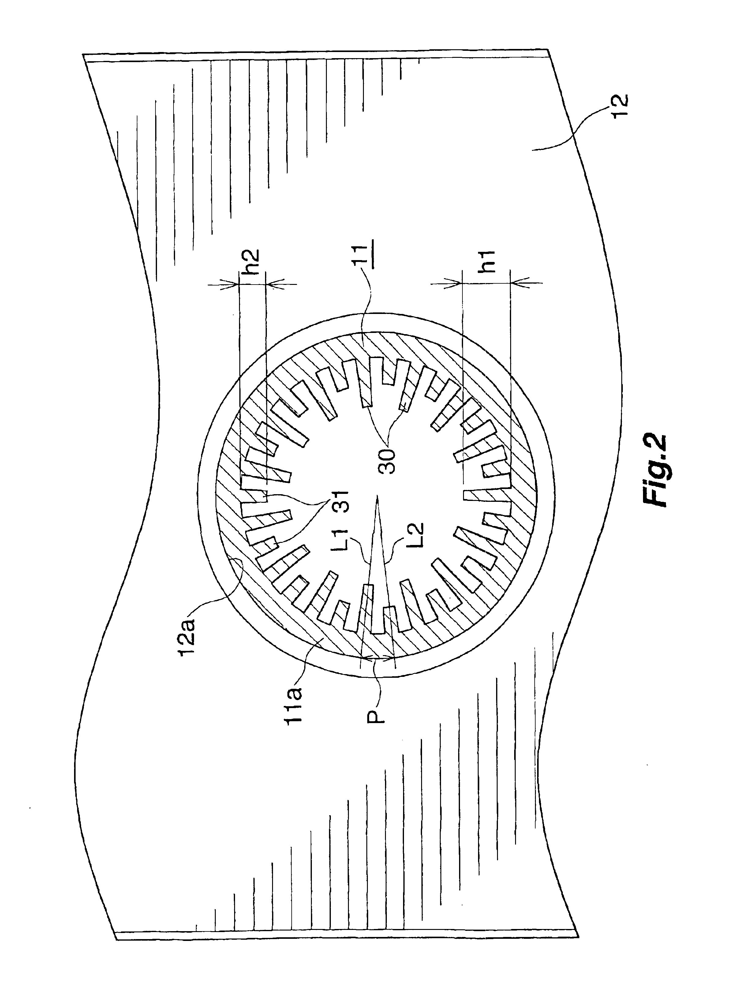
[0087]Prepared were a heat exchanger 1 (invention device 1) comprising a hairpin tube 11 having the cross section shown inFIG. 2, and a heat exchanger 1 (invention device 2) comprising a hairpin tube 11 having the cross section shown in FIG. 7. The hairpin tube 11 of the heat exchanger 1 as the invention device 1 was 8 mm in outside diameter, 0.61 mm in circumferential wall thickness, 1.2 mm in the height h1 of projection of high inner fins 30, 0.65 mm in the height h2 of projection of low inner fins 31, and 30 in the combined number of two kinds of inner fins 30, 31. The hairpin tube 11 of the heat exchanger 1 as the invention device 2 was 8 mm in outside diameter, 0.61 mm in circumferential wall thickness, 1.2 mm in the height h3 of projection of inner fins 32, and 30 in the number of inner fins 32.

[0088]Also prepared was a heat exchanger (comparative device 1) having the same construction as the invention device 1 except that the hairpin tube 40 used had the cross section shown i...

experimental example 2

[0090]Evaporators comprising the invention devices 1, 2 and comparative device 1 were incorporated into refrigerators, which were installed in an atmosphere having a temperature of 25° C. and relative humidity of 70%. The refrigerators were then tested for power consumption by operating the compressor intermittently by on / off control with the door closed. As a result, the refrigerator incorporating the invention device 1 as its evaporator was found to be 2% lower in power consumption than the refrigerator incorporating the comparative device 1 as the evaporator. Similarly, the refrigerator incorporating the invention device 2 as its evaporator was 1.3% lower in power consumption than the refrigerator incorporating the comparative device I as the evaporator.


PUM

PropertyMeasurementUnit
Lengthaaaaaaaaaa
Thicknessaaaaaaaaaa
Thicknessaaaaaaaaaa

Abstract

A heat exchanger finned tube 10 for use in fabricating a heat exchanger 1 useful as the evaporator for refrigerators or the like wherein a hydrocarbon refrigerant is used. Two tube insertion holes spaced apart from each other are formed in each of plate fins 12, and two straight tube portions 11a of a hairpin tube 11 are inserted through the respective holes of each plate fin to arrange the plate fins 12 in parallel into a plurality of fin groups 13 spaced apart on the straight tube portions 11a longitudinally thereof. The hairpin tube 11 is enlarged with use of a fluid to fixedly fit the plate fins 12 of each tin group 13 around an enlarged tube portion 14 of the hairpin tube 11 and provide a finless part 19 between each pair of adjacent fin groups 13 on each of the straight tube portions 11a. A restrained small-diameter portion 15 is provided in each of the finless parts 19 of each straight tube portion 11a. The heat exchanger 1 fabricated using the finned tube 10 exhibits the desired refrigeration performance with the leakage of refrigerant diminished.

Description

CROSS REFERENCE TO RELATED APPLICATIONS[0001]This application is an application filed under 35 U.S.C. §111(a) claiming the benefit pursuant to 35 U.S.C. §119(e)(1) of the filing date of Provisional Application No. 60 / 331,210 filed Nov. 13, 2001 pursuant to 35 U.S.C. §111(b).TECHNICAL FIELD[0002]The present invention relates to heat exchanger finned tubes for use in fabricating heat exchangers useful as evaporators of refrigeration devices such as refrigerators and refrigerated showcases, heat exchangers, a process for producing the finned tube and a process for fabricating the heat exchanger.BACKGROUND ART[0003]As evaporators of refrigeration devices such as refrigerators and refrigerated showcases, heat exchangers are in use which comprise a heat exchanger finned tube and formed in a zigzag shape in its entirety by bending the finned tube at a plurality of finless portions thereof. The finned tube comprises a hairpin tube, and a plurality of fin groups which are arranged on two str...

Claims


Application Information

Patent Timeline
IPC IPC(8): B21D53/08B21D53/02F25B39/02F28D1/047F28F1/32F28F1/40
CPCB21D53/085F25B39/02F28F1/32F28F1/40F28D1/0477Y10T29/49375
Inventor WATANABE, ISAOMARUGASA, SHIGEO
Owner SHOWA DENKO KK
Why Eureka
Try Eureka