High-pressure fuel injection pipe

a fuel injection pipe and high-pressure technology, applied in the direction of sleeves/socket joints, mechanical equipment, machines/engines, etc., can solve the problems of easy increase in fold crimp on the inner surface, and deterioration of mechanical strength, so as to improve mechanical strength, reduce cracking or bending damage caused by vibration, and prevent the effect of cracking or bending damag

Active Publication Date: 2005-01-18
USUI KOKUSAI SANGYO KAISHA LTD
View PDF27 Cites 30 Cited by
  • Summary
  • Abstract
  • Description
  • Claims
  • Application Information

AI Technical Summary

Benefits of technology

However, in the high-pressure fuel injection pipe of this type, there is a problem in that concentration of a stress may occur due to a bending load or the like caused by vibrations of an under-head portion R of the connecting head portion 13 because of the structure of the pipe diameter portion 14 formed simply of the metallic pipe itself which corresponds to the portion in the vicinity of the under-head portion of the connecting head portion 13, and the loosely fitted structure at the pipe diameter portion 14 of the washer 15, whereby deterioration of mechanical strength and hence local fatigue are resulted, thereby generating cracking or bending damages easily.
In view of such problems of the related art as described above, it is an object of the present invention to provide a high-pressure fuel injection pipe in which concentration of a stress to the portion under the connecting head portion generated by a bending load or the like caused by vibrations can be effectively alleviated.
As described above, according to the present invention, since the high-pressure fuel injection pipe is provided with the thick wall portion or the tapered wall continuing to the straight pipe portion, which satisfies the adequate conditions, is provided at the under-head portion of the connecting head portion, concentration of a stress to the portion in the vicinity of the under-head portion can be alleviated and hence the mechanical strength can be improved, whereby cracking or bending damages due to a bending load or the like caused by vibrations can significantly be reduced or prevented, and hence a stable connection and durability can be maintained for a long time.

Problems solved by technology

However, in the high-pressure fuel injection pipe of this type, there is a problem in that concentration of a stress may occur due to a bending load or the like caused by vibrations of an under-head portion R of the connecting head portion 13 because of the structure of the pipe diameter portion 14 formed simply of the metallic pipe itself which corresponds to the portion in the vicinity of the under-head portion of the connecting head portion 13, and the loosely fitted structure at the pipe diameter portion 14 of the washer 15, whereby deterioration of mechanical strength and hence local fatigue are resulted, thereby generating cracking or bending damages easily.
However, increasing the area of the flange 13′ by increasing the diameter thereof may result in increase in fold crimp formed on the inner surface of the pipe at the time of buckling molding (molding of the terminal), and hence the strength against the internal pressure may be lowered.
Therefore, the size of the flange 13′ is limited, and hence the measure to increase the diameter of the flange 13′ is not necessarily effective measure for alleviating concentration of the stress.

Method used


Image

  • High-pressure fuel injection pipe
  • High-pressure fuel injection pipe
  • High-pressure fuel injection pipe

Examples


example 1

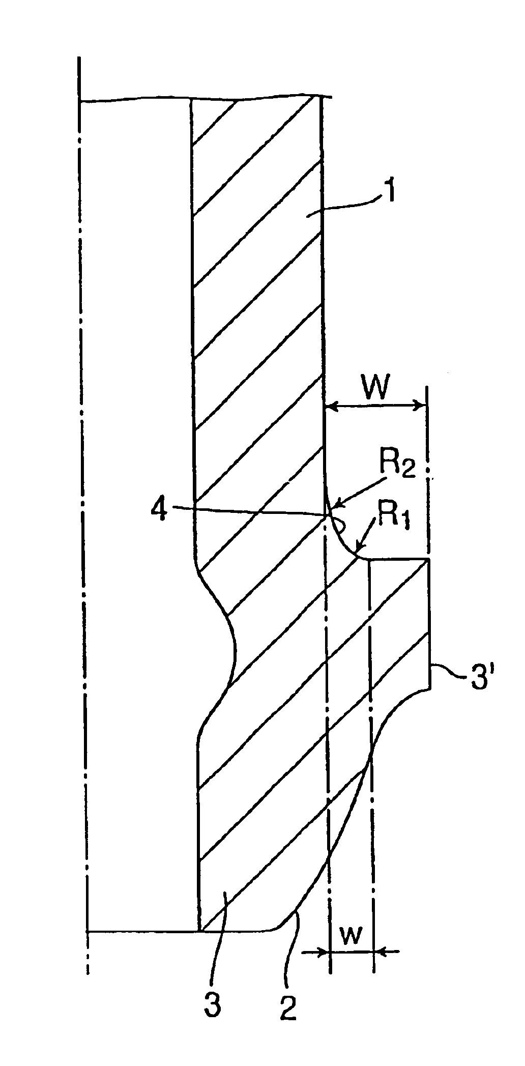
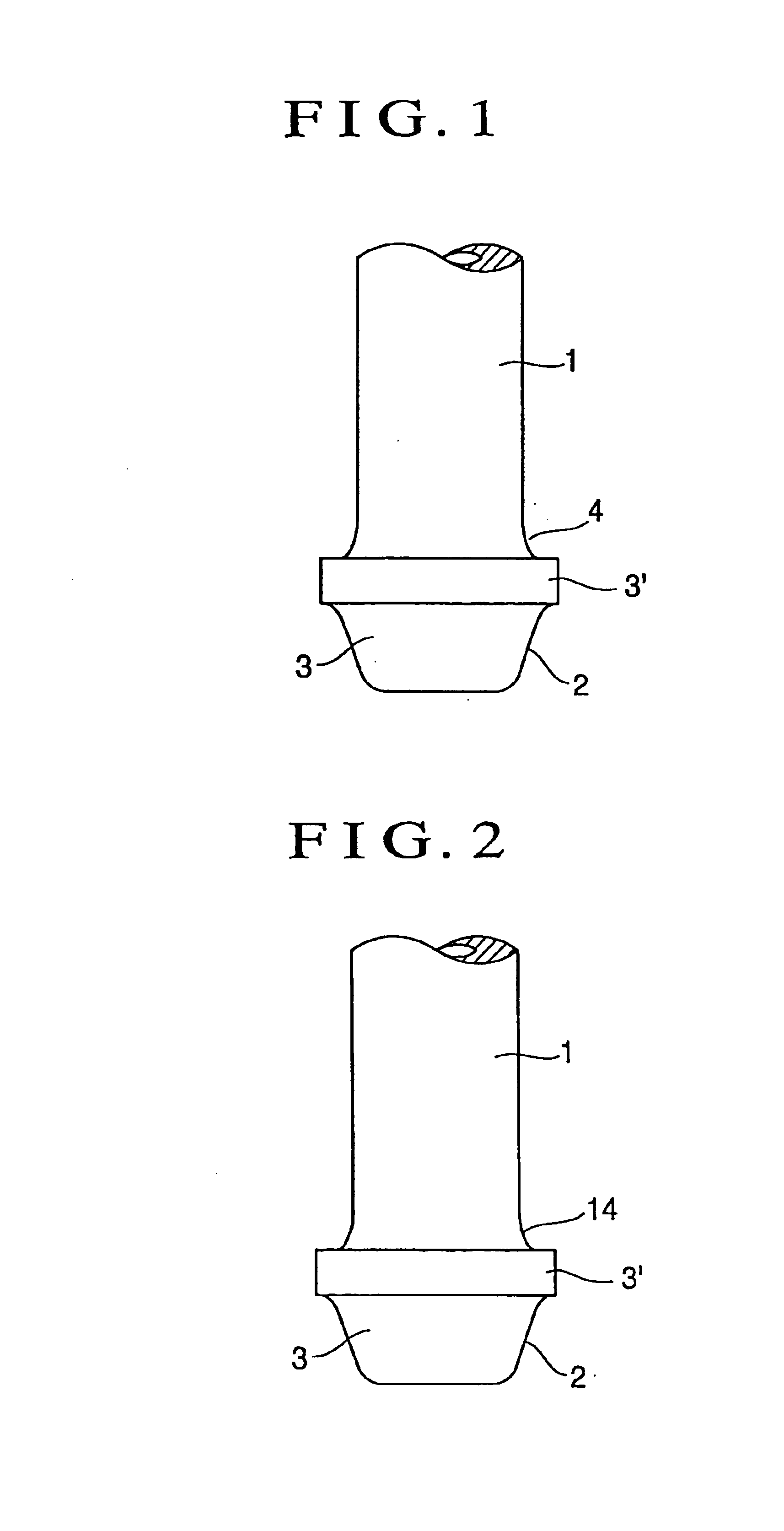
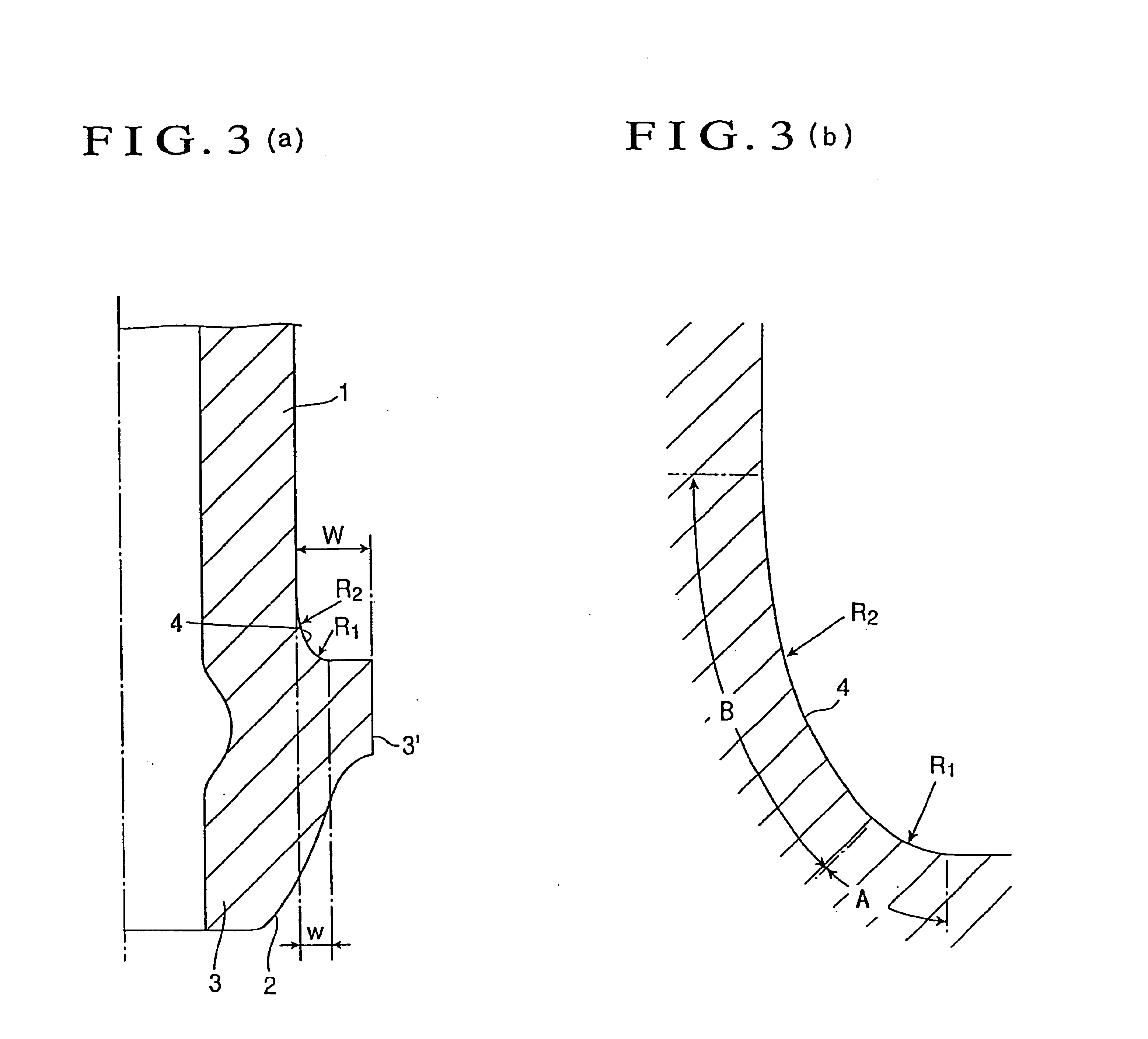
The result of a fatigue characteristics test conducted for a high-pressure fuel injection pipe having a thick wall portion that satisfies the conditions in 1 to 3 described above and a high-pressure fuel injection pipe in the related art having a shape without the thick wall portion as shown in FIG. 5 using a thick and small-diameter metallic pipe of 3 mm in inner diameter and 6.35 mm in outer diameter formed of STS410 is shown in Table 1.

As is clear from the result shown in Table 1, in the high-pressure fuel injection pipe according to the present invention, concentration of a stress to an under-head portion of a connecting head portion was alleviated and hence the generated stress could be reduced in comparison with the pipe in the related art.

TABLE 1Thick Wall PortionMaximumTest Piece No.R1(mm)R2(mm)w(mm)Stress (MPa)Invention10.230.519720.330.520330.430.520640.440.520750.29.50.519761.031.45149Comparative0.4—0.4252Example

example 2

The result of the fatigue characteristic test conducted for a high-pressure fuel injection pipe having a thick wall portion that satisfies the conditions in 4 to 7 described above and a high-pressure fuel injection pipe in the related art having a shape without the kick wall portion as shown in FIG. 5 using a thick and small-diameter metallic pipe of 4 mm in inner diameter and 10 mm in outer diameter formed of STS 410 is shown in Table 2.

As is clear from the result shown in Table 2, the high-pressure fuel injection pipe according to the present invention in this example as well, concentration of a stress to the under-head portion of the connecting head portion was alleviated and hence the generated stress could be reduced in comparison with the pipe in the related art.

TABLE 2Tapered WallMaximumTest Piece No.θ(°)R1 (mm)R2 (mm)w (mm)Stress (MPa)Invention17.50.310.52282100.310.52373150.310.5203Comparative100.4—0.4252Example240.310.5240


PUM

PropertyMeasurementUnit
inner diameteraaaaaaaaaa
angleaaaaaaaaaa
outer diameteraaaaaaaaaa

Abstract

A high-pressure fuel injection pipe has a connecting head portion increased in diameter by buckling molding at the end of a thick and small-diameter metallic pipe. An under-head portion of the connecting head is formed with a thick wall portion that satisfies conditions of: a radius of curvature R1 of a portion A of the thick wall portion continuing to the connecting head is 0.03 to 0.15 times the outer diameter of the pipe; a radius of curvature R2 of a portion B continuing from the portion A of the thick wall portion to a straight pipe portion is 0.3 to 1.5 times the outer diameter of the pipe; and a maximum diametrical size w of the thick wall portion is 0.25 to 0.4 times a maximum diametrical projecting length W of the connecting head.

Description

BACKGROUND OF THE INVENTION1. Technical FieldThe present invention relates to a high-pressure fuel injection pipe generally provided and used as a fuel supply channel in a diesel internal combustion engine and formed of a relatively thick and small-diameter metallic pipe and, more specifically, to a high-pressure fuel injection pipe which can alleviate concentration of a stress to an under-head portion at the terminal due to a bending load or the like caused by vibrations.2. Background ArtIn the background art, there is a known high-pressure fuel injection pipe of this type formed of a thick and small-diameter metallic pipe 11 provided at the end thereof with a connecting head portion 13 of a truncated arcuate shape having a spherical pressing seat surface 12 on its outer periphery formed by buckling molding. The high-pressure fuel injection pipe of this type is connected by loosely fitting a ring-shaped washer 15 or a sleeve washer (not shown) to a pipe diameter portion 14 of the t...

Claims


Application Information

Patent Timeline
Patent Type & Authority Patents(United States)
IPC IPC(8): F02M55/02F02M55/00F16L19/02F16L19/028F02M61/16F02M61/18
CPCF02M55/02F16L19/028F16L19/0225F16L19/0283F16L21/002F02M55/00F02M61/16F02M61/18
Inventor KATO, NOBUO
Owner USUI KOKUSAI SANGYO KAISHA LTD
Why Eureka
Try Eureka