Pneumatic nail gun having nail pusher

a nail gun and pneumatic technology, applied in the field of nail guns with pneumatic nail guns, can solve the problems of low stability of the movement insufficient and the limited high pressure air in the air collection chamber. to achieve the effect of enhancing the speed of repositioning of the nail pushing piston

Inactive Publication Date: 2007-11-20
DE POAN PNEUMATIC
View PDF11 Cites 25 Cited by
  • Summary
  • Abstract
  • Description
  • Claims
  • Application Information

AI Technical Summary

Benefits of technology

[0007]In an alternative modification, the pneumatic nail gun further includes an exhausting hole connecting with environment that is disposed at an inner surface of the nail pushing cylinder or the nail pushing piston, which can enhance the speed of reposition of the nail pushing piston after the next nail was taken. Moreover, the exhausting hole has a cross section farther smaller than the cross section of the nail pushing passage, which can help to maintain the air pressure of the high pressure air in the nail pushing cylinder and prevent the high pressure air from exhausting from the nail pushing cylinder too fast.

Problems solved by technology

However, the air collection chamber can just receive limited high pressure air when the nail punching piston moves downward.
Therefore, the limited high pressure air in the air collection chamber is not sufficient to drive the nail pushing piston to take the next nail for being driven and drive the nail punching piston to the original position, particularly in the process of continuously punching and pushing the nails.
That is, the stability of the movement of the nail pushing piston is low, and the instability upward movement of the nail punching piston lowers the speed and efficiency of punching the nail.

Method used


Image

  • Pneumatic nail gun having nail pusher
  • Pneumatic nail gun having nail pusher
  • Pneumatic nail gun having nail pusher

Examples


Embodiment Construction

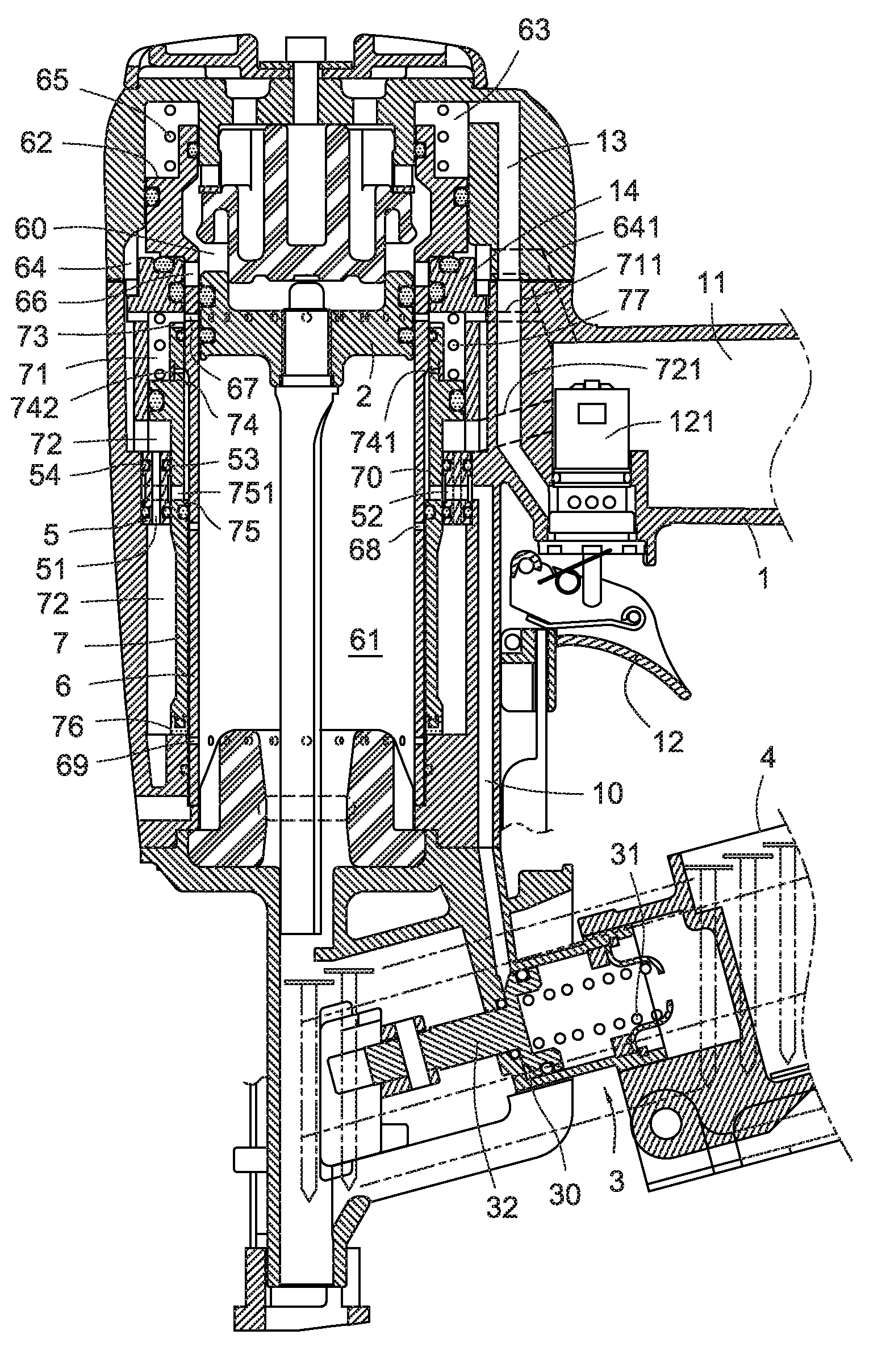
[0018]Referring to FIG. 1, an exemplary pneumatic nail gun according to the present invention is shown. The pneumatic nail gun includes a gun body 1, a nail pusher 3, and an air distribution ring 5 (shown in FIG. 2).

[0019]The gun body 1 includes a nail punching piston 2 and a nail pushing passage 10. The nail punching piston 2 is induced by high pressure air to move downwardly to punch the nails and move upwardly to reposition.

[0020]The nail pusher 3 is disposed between an end of the nail pushing passage 10 and a canister 4. The nail pusher 3 includes a nail pushing cylinder 30 (shown in FIG. 6) connecting to the nail pushing passage 10, and the nail pushing cylinder 30 includes a nail pushing piston 32 and a spring 31 therein.

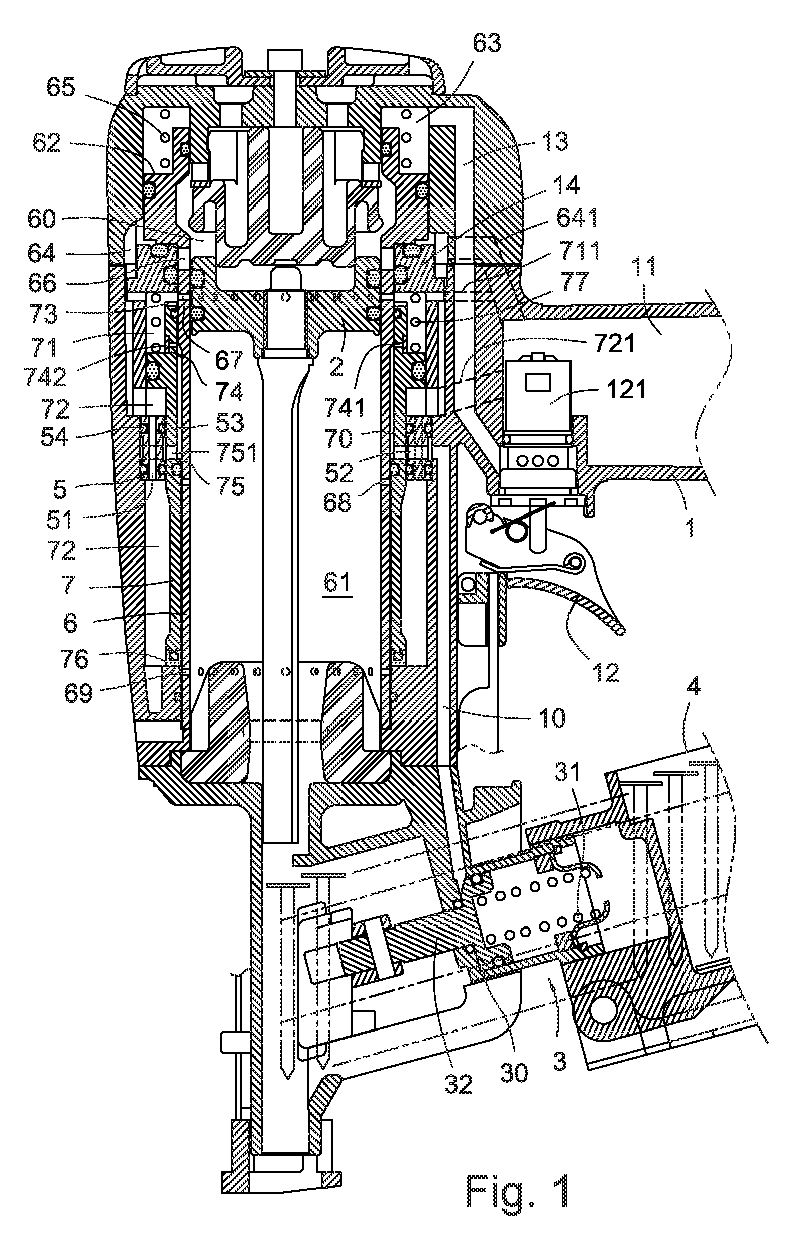
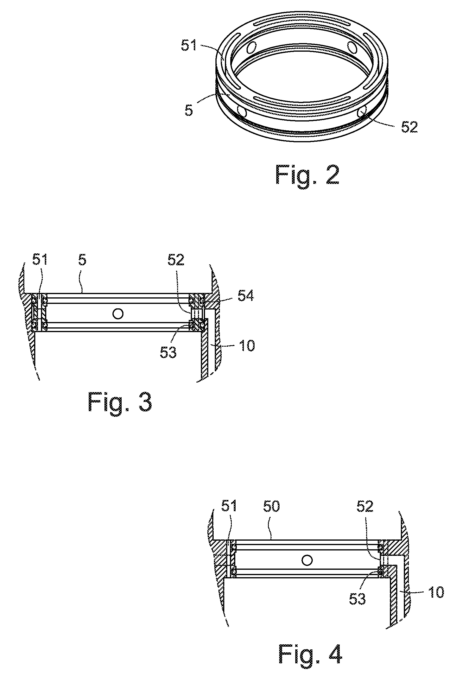
[0021]The air distribution ring 5 includes at least one axial through hole 51 and at least one radial through hole 52. The air distribution ring 5 is fixed to an inner surface of the gun body 1 via nesting (shown in FIG. 3) or integrally formed with (shown in ...


PUM

PropertyMeasurementUnit
pressureaaaaaaaaaa
structureaaaaaaaaaa
stabilityaaaaaaaaaa

Abstract

An exemplary pneumatic nail gun includes a gun body having a nail punching piston and a nail pushing passage. A nail pusher has a nail pushing cylinder connecting to the nail pushing passage. The nail pushing cylinder includes a nail pushing piston and a spring. An air distribution ring having an axial through hole and a radial through hole. The axial through hole guides the high pressure air to drive the nail punching piston to reposition after the nail punching piston downwardly moving to punch the nails. The radial through hole guides the high pressure air into the nail pushing cylinder via the nail pushing passage to drive the nail pushing piston to take the nails, and also exhaust the high pressure air in the nail pushing cylinder and the nail pushing passage to make the nail pushing piston reposition to push the nails when the nail punching piston reposition.

Description

BACKGROUND[0001]The present invention relates to a nail gun with a nail pusher, and particularly to a pneumatic nail gun having an air distribution ring being used for guiding high pressure air to drive or release a nail pushing position of a nail pusher.[0002]Pneumatic nail gun generally utilizes a compressed high pressure air to drive a piston to punch a nail, for joining two objects by shooting a nail through both objects. A typical pneumatic nail gun includes a gun body having a cylinder and a nail punching piston dividing the cylinder into a top air chamber and a bottom air chamber. When a trigger of the gun body is triggered, high pressure air is introduced into the top air chamber for driving the nail punching piston to move downward, to punch the nail. In a reverse case, when the trigger is released, the high pressure air in the top air chamber is exhausted, and other high pressure air is introduced into the bottom air chamber to reposition the nail punching piston.[0003]A c...

Claims


Application Information

Patent Timeline
Patent Type & Authority Patents(United States)
IPC IPC(8): B25C1/04
CPCB25C1/045
Inventor WEN, WAN-FU
Owner DE POAN PNEUMATIC
Why Eureka
Try Eureka