Turbine-integrated hydrofoil

a hydrofoil and turbine technology, applied in the direction of electric generator control, vessel auxillary drive, underwater equipment, etc., can solve the problems of large energy supply from such an expansive source, relatively few have considered a mobile structure, and structures that do not adequately address energy delivery, etc., to achieve optimal energy, reduce environmental impact, facilitate maintenance of overall stability and guidance of the vessel

Inactive Publication Date: 2007-11-20
INTEGRATED POWER TECH CORP
View PDF18 Cites 56 Cited by
  • Summary
  • Abstract
  • Description
  • Claims
  • Application Information

AI Technical Summary

Benefits of technology

[0007]The present invention achieves the goals of overcoming existing limitations of prior art oceanic hydrokinetic and pneumatic power generation systems foremost through integration into a singular generation and delivery system to extract power from free-flowing seawater while simultaneously exploiting wind energy. While prior art exists which functions in free-flowing bodies of water or wind, the novelty of this invention lies in its ability to respond and adapt to any change in the magnitude and direction of the streamlines of plural free-flowing motive fluids while controlling drag caused by moving in any direction within the mediums of wind and water. Through implementing a system to control vessel velocity given input parameters such as wind velocity, seawater current velocity, vessel mass and drag affecting actual velocity of the vessel, and feedback of generator output voltages; this enables the present invention to extract optimal energy from both pneumatic and hydrokinetic sources. Controlling the drag also facilitates maintaining overall stability and guidance of the vessel.
[0008]Secondly, because developing an integrated generation and delivery system which optimally adapts to changes in both magnitude and direction of the streamlines of plural free-flowing motive fluids formed the basis of the guiding concepts of the present invention; this readily avails the present invention the applicability to any body of water anywhere. Thus, the present invention does not require a large scale of infrastructure and therefore greatly diminishes the environmental impact while attaining a positive net energy earlier upon implementation.

Problems solved by technology

Utmost, to optimally exploit oceanic energy, which may be attained anywhere over approximately three quarters of the surface of the planet thus availing vast industrial growth potential, the main obstacle existing is the delivery from such an expansive source of energy.
While many patents exist for harnessing energy from pneumatic and hydraulic sources, relatively few have considered a mobile structure to facilitate delivery of energy and maintenance and servicing of the structure.
These types of structures obviously do not adequately address delivery of energy considering their distance from the shore, the actual distribution center.
These structures also impede maritime traffic and present maintenance difficulties especially in severe weather conditions.
The prior art structures utilizing hydrokinetic turbines yield power limited by the velocity of the motive fluid converted from wave motion alone.

Method used


Image

  • Turbine-integrated hydrofoil
  • Turbine-integrated hydrofoil
  • Turbine-integrated hydrofoil

Examples


Embodiment Construction

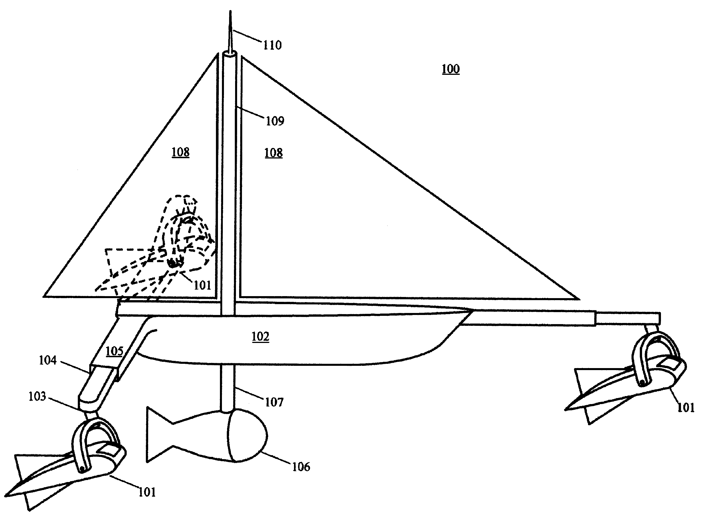
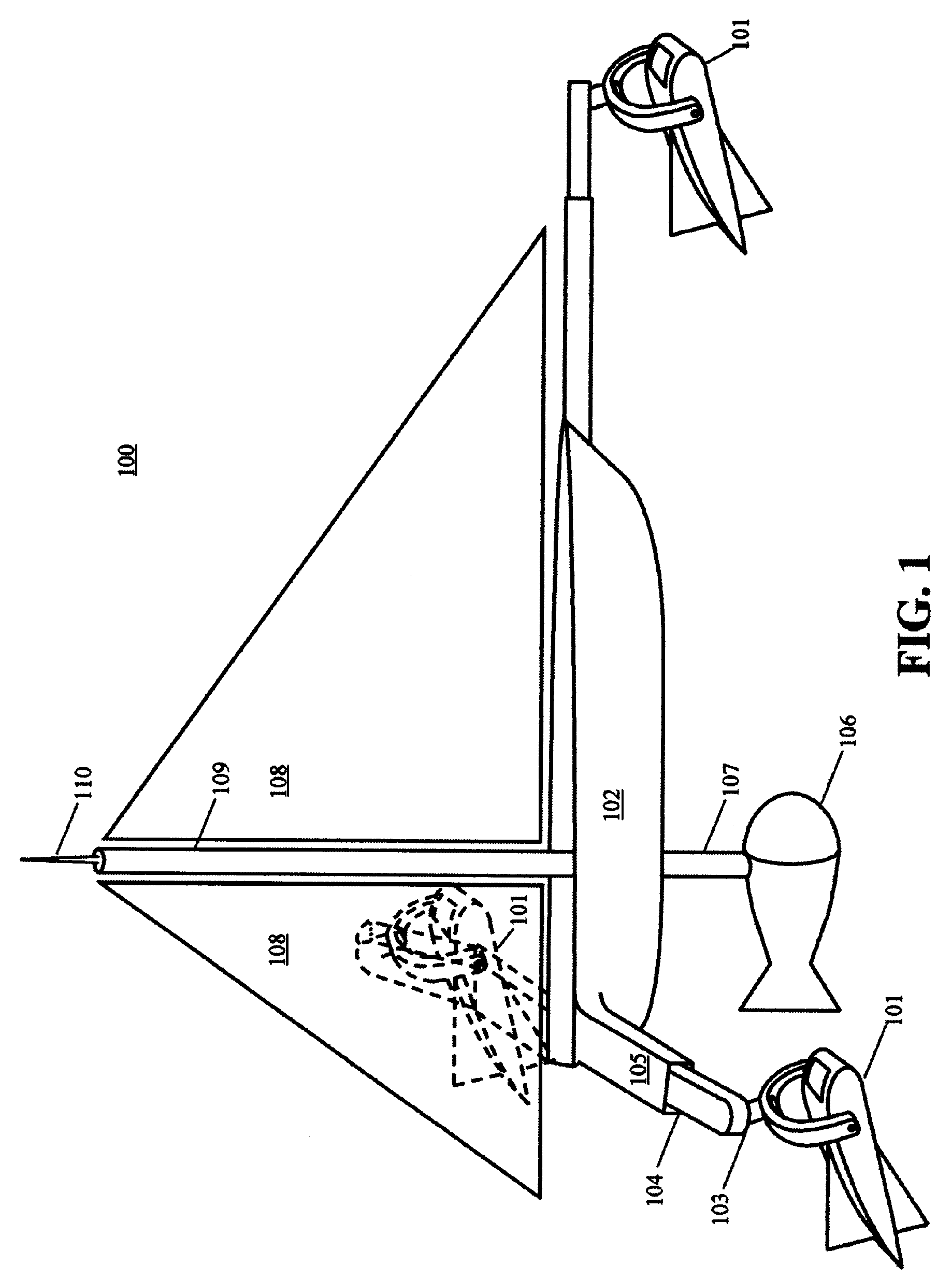
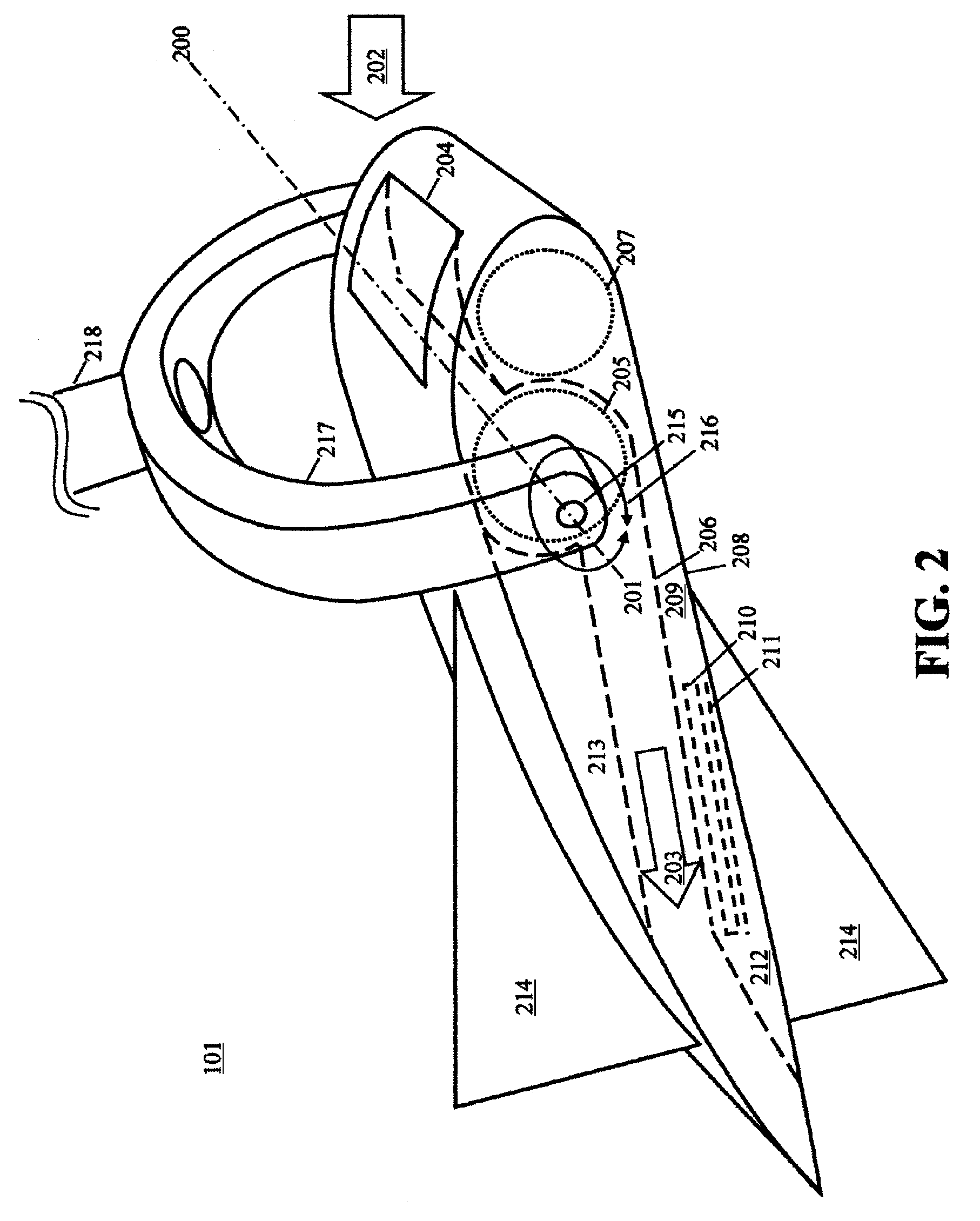
[0018]The present invention is directed to a turbine-integrated hydrofoil for adaptively extracting energy from plural free-flowing motive fluids that continuously change direction and magnitude of flow. The following description contains specific information pertaining to various embodiments and implementations of the present invention. One skilled in the art will recognize that the present invention may be implemented in a manner different from that specifically depicted in the present specification. Furthermore, some of the specific details of the invention are not described in order to maintain brevity and to not obscure the invention. The specific details not described in the present specification are within the knowledge of a person of ordinary skills in the art. Obviously, some features of the present invention may be omitted or only partially implemented and remain well within the scope and spirit of the present invention.

[0019]The following drawings and their accompanying d...


PUM


Abstract

A turbine integrated within a hydrofoil extracts energy from a free-flowing motive fluid. In the preferred embodiment, the turbine is of the crossflow variety with runner blades coaxial to the width of the hydrofoil. The foremost edge of the hydrofoil comprises a slot covered by a continuously adjustable gate for controlling the overall drag imposed by the turbine. The hydrofoil mounts to a sailing vessel by means of a gimbal on a structure affixed to the hull, enabling the turbine to optimally respond to changes in direction of the free-flowing motive fluid and facilitating guidance and stability of the vessel. Both axes of the gimbal have a combination of auxiliary generator and motor with a locking mechanism. Engaging the motor and locking mechanism controls the guidance and stability of the overall vessel, and the pitch of the hydrofoil. Disengaging the locking mechanism and motor permits any change in direction of the motive fluid to affect the gimbal thereby extracting energy via the auxiliary generators. To further control drag and output power over a range of flow velocities, the preferred turbine comprises a DC generator with voltage feedback controlling field excitation, coupled to a voltage and current regulating circuit that performs electrolysis of water to produce hydrogen fuel. The hydrogen fuel tank also functions as the vessel's ballast having adjustable draft depending upon its fullness. Integrated remote control simultaneously optimizes vessel guidance, velocity, drag, stability, ballast depth, and electrolysis processes.

Description

BACKGROUND OF THE INVENTION[0001]1. Field of the Invention[0002]The present invention is generally in the field of power plants. More specifically, the present invention is in the field of hydrokinetic generators with means to adapt to changes in streamline direction and magnitude of a free-flowing motive fluid. Most importantly, the present invention maximizes net energy by utilizing a hydrokinetic generator mounted on a marine sailing vessel that also limits drag on the vessel in a controlled manner.[0003]2. Description of Prior Art[0004]Considering present humankind's primary source of energy, fossil fuel can diminish to the point of negligible net energy within this century; there exists a fundamental need for developing renewable and sustainable sources of energy including further exploitation of readily available known resources. More specifically, there exists a need for a novel approach to ensure least impact to environment and low civic infrastructure costs such that the en...

Claims


Application Information

Patent Timeline
Patent Type & Authority Patents(United States)
IPC IPC(8): B63G8/42
CPCB63B1/24B63J3/04F03B17/06F03B17/062B63H9/04C25B1/04F01D25/24H02K7/1823H02P9/04Y02E10/38B63B2035/4466F05B2210/18F05B2220/61F05B2240/931Y02E10/28Y02E70/10Y02T90/38Y02E60/366Y02T70/583B63B2035/009Y02E10/20Y02E10/30Y02E60/36Y02T70/5236Y02T90/40
Inventor GIZARA, ANDREW ROMAN
Owner INTEGRATED POWER TECH CORP
Why Eureka
Try Eureka