Eccentric venturi flow meter

Active Publication Date: 2007-11-27
DIETERICH STANDARD
View PDF3 Cites 40 Cited by
  • Summary
  • Abstract
  • Description
  • Claims
  • Application Information

AI Technical Summary

Problems solved by technology

One such disadvantage is the propensity of the changing profiles of the venturi tube to precipitate and collect sediment or solids from fluids having entrained solid materials, such as slurries and sanitary flows.
Accumulation of this sediment, especially in the profile changes along the bottom interior surfaces of the venturi tube, clogs the flow meter and degrades its performance by upsetting its calibration.
Accordingly, their structural limitations could not support their use as a flow measurement instrument.

Method used


Image

  • Eccentric venturi flow meter
  • Eccentric venturi flow meter
  • Eccentric venturi flow meter

Examples


Embodiment Construction

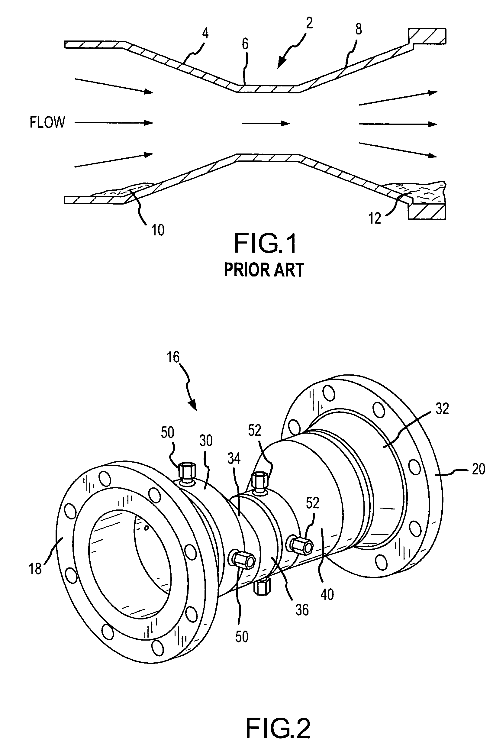
[0015]Referring first to FIG. 1, a diagrammatic longitudinal cross section of a traditional prior art venturi tube is shown. The tube 2 has a tapered upstream section 4 that converges into a coaxial reduced diameter throat 6 and expands into a coaxial divergent downstream section 8. At the points 10 and 12, along the bottom surface of the tube, sediment or other foreign material has been deposited at the points of vertical change in the contour of the floor of the venturi tube is shown. Such deposits change the flow characteristics of the fluid in the tube and destroy the accuracy of the calibration of the flow meter.

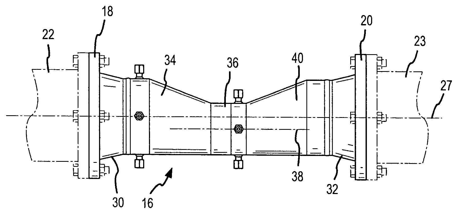
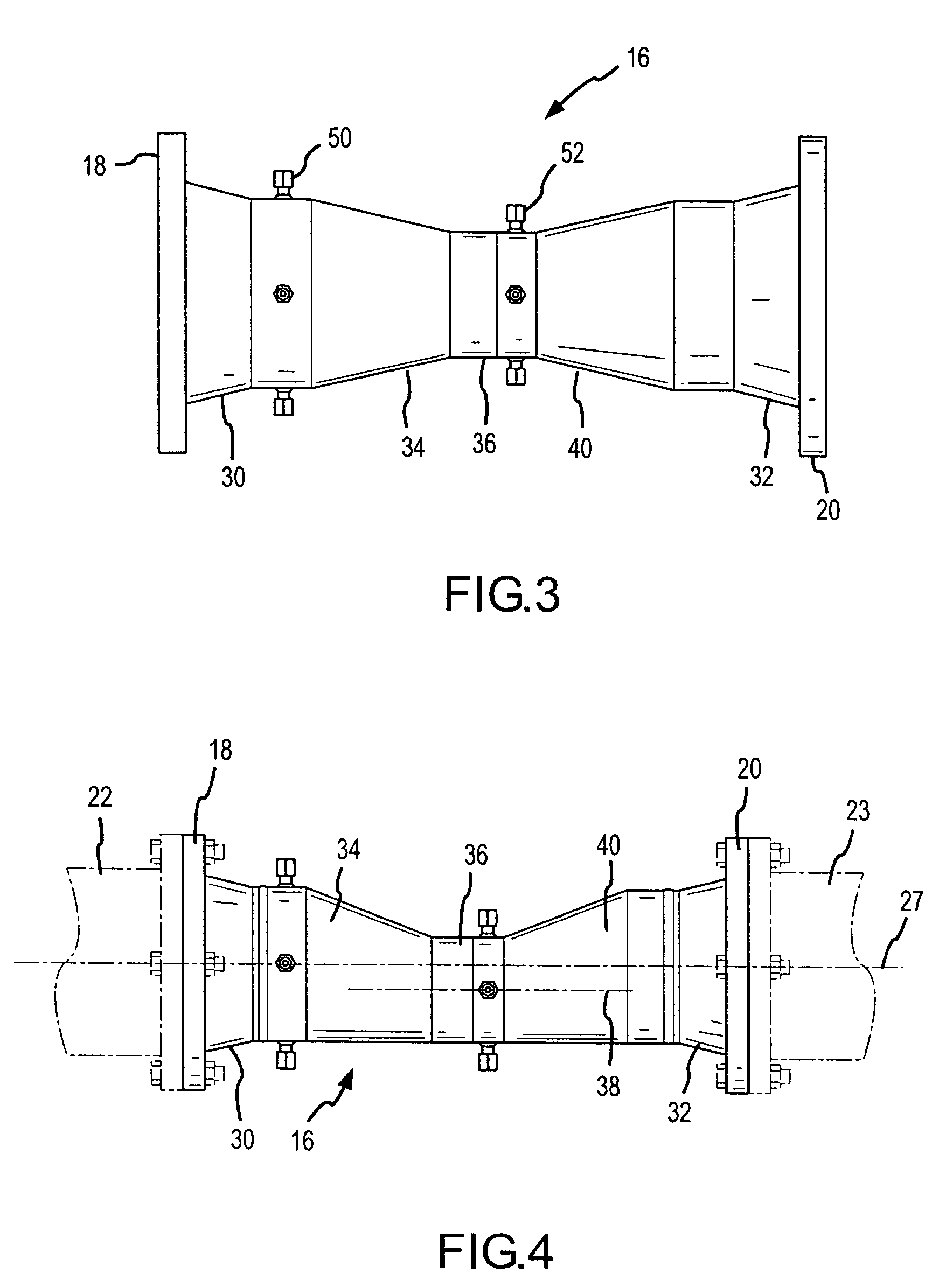
[0016]The structural elements of the eccentric flow meter of the present invention are best seen in FIGS. 4 and 5 of the drawings. The eccentric flow meter comprises a hollow flow body 16 on each end of which are attached pipe flanges 18 and 20. While pipe flanges are shown in a preferred form of the invention, threaded pipe couplings, pipe clamps, welding or other pipe...


PUM


Abstract

A venturi type of primary flow element comprising a tubular body defining a flow path having open ends and walls and including in series, a converging section, a cylindrical throat section, and a diverging section, where the bottom walls of each of said sections are in alignment and present a smooth unangled surface to flowing fluid therein.

Description

FIELD OF THE INVENTION[0001]The present invention relates to a venturi type of primary rate of fluid flow measuring element for determining differential fluid pressure existing at spaced apart points in the flow element.BACKGROUND OF THE INVENTION[0002]Venturi tube flow meters are a species of differential pressure flow meters that infer a rate of a fluid flow in a closed piping system from a measurement of differential pressure that is caused by a change of kinetic energy in the fluid. The pressure drop across the flow meter is proportional to the square of the flow rate. The change of kinetic energy in a flowing fluid can be created by various types of flow measurement devices such as for example, orifice plates, pitot tubes, flow nozzles, wedge meters and venturi tubes.[0003]Venturi tubes have the advantage of being able to handle large flow volumes while creating only low permanent pressure loss in the system. A venturi tube is essentially a section of pipe having a tapered upst...

Claims


Application Information

Patent Timeline
IPC IPC(8): G01F1/44
CPCG01F1/44
Inventor EVANS, RUSSELL N.
Owner DIETERICH STANDARD
Why Eureka
Try Eureka