
Paper trimmer

a technology of paper trimmer and blade, which is applied in the field of paper trimmer, can solve the problems of posing a significant danger, difficult to easily and conveniently transport the blade for personal use, and the exposed elongated blade is difficult to easily and conveniently assemble, and achieves the effects of simple operation, increased safety, and simple assembly

Active Publication Date: 2007-11-27
ALTERRA HLDG
View PDF38 Cites 27 Cited by
  • Summary
  • Abstract
  • Description
  • Claims
  • Application Information

AI Technical Summary

Benefits of technology

"The present invention is an improved paper trimmer that consistently cuts paper in straight lines. It is designed to provide a straight cut even in the presence of varying forces applied to the blade carriage. It is relatively simple to assemble and operate, and it is relatively safe. The invention includes a base, a plate, a carrier, and a blade. The plate is movably attached to the base and includes an elongated slot, elevated portions, and an arcuate surface. The carrier includes a top flange and a foot that slidably receives the slot. The blade is attached to the carrier, and a portion of it extends below the lower surface of the plate within the channel when the plate is disposed over the cutting region. The slot has a first width at the first and second ends thereof and a second width between the first and second ends, the first width being larger than the second width, which makes it easy to insert and remove the carrier from the paper cutter."

Problems solved by technology

The elongated blade is often exposed, posing a significant danger, especially for use by children.
Another drawback of this type of cutter is the overall size which makes it difficult to easily and conveniently transport them for personal use.
Another limitation of conventional cutters is the number of variables which may influence the straightness of the cut.

Method used


Image

  • Paper trimmer
  • Paper trimmer
  • Paper trimmer

Examples


Embodiment Construction

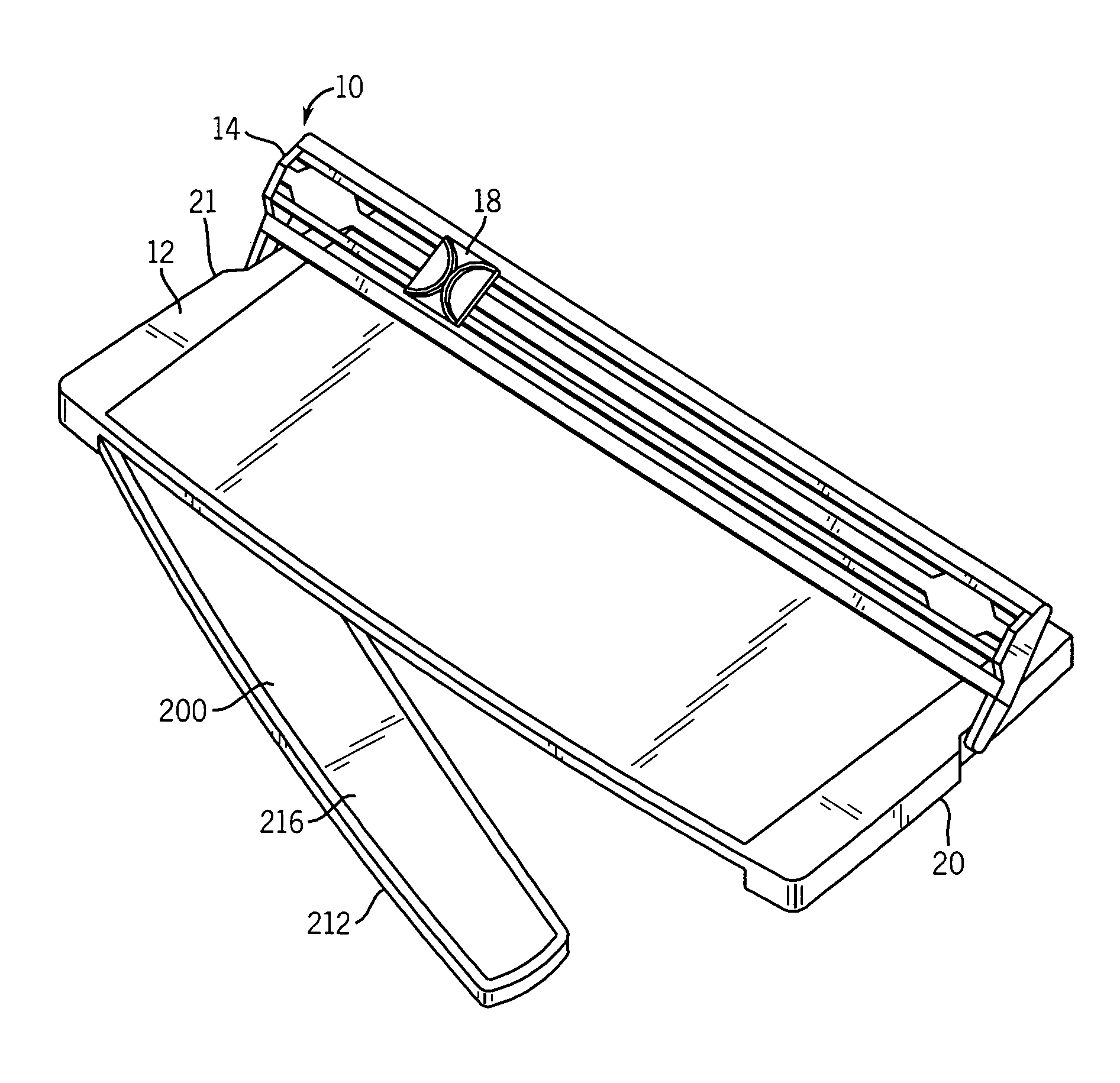
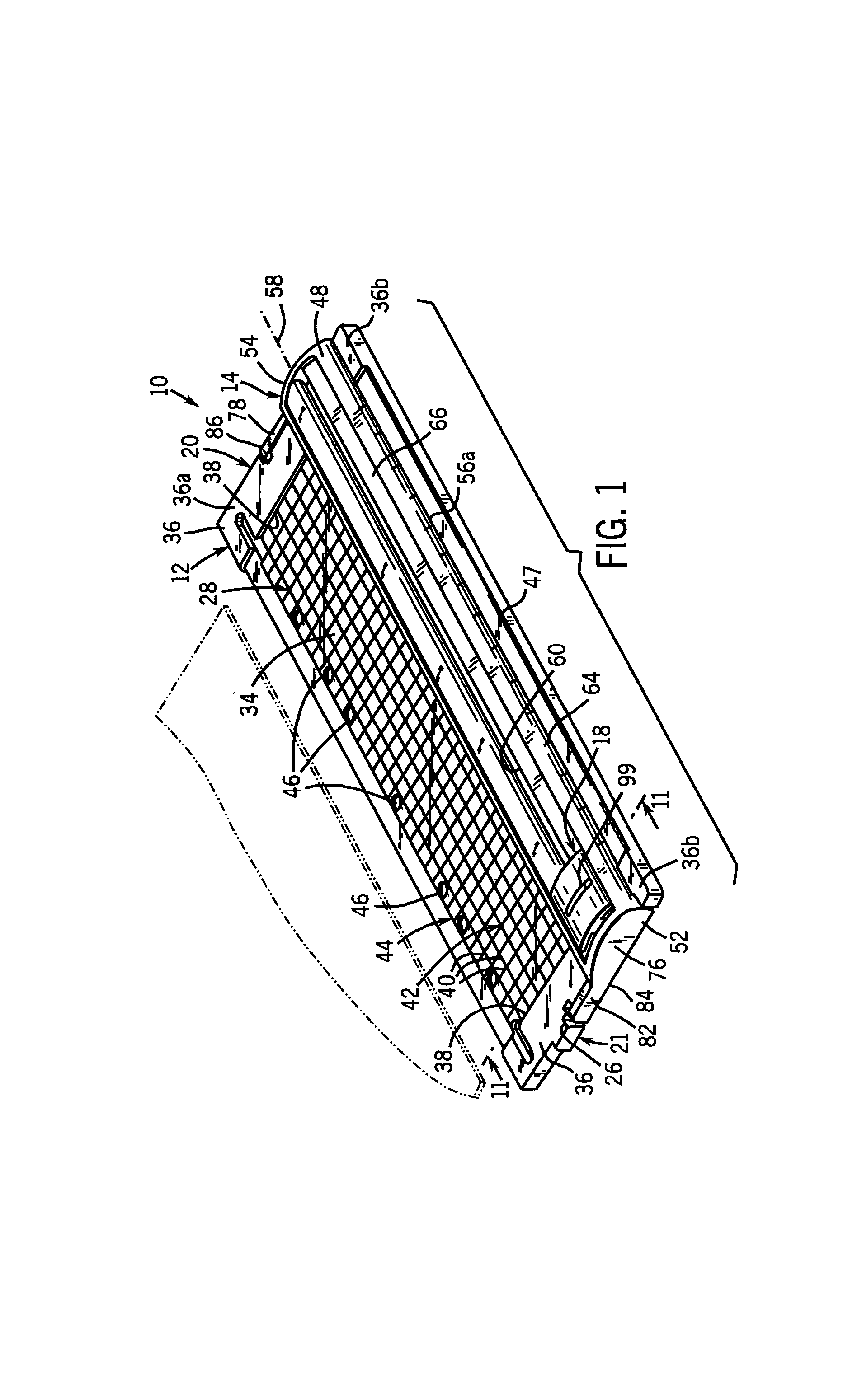
[0030]A paper trimmer constructed in accordance with the present invention is shown generally at 10 in FIGS. 1–2. The paper trimmer 10 includes a base 12 and an elongated plate 14 pivotally attached to base 12. A blade assembly 16 is attached to a carrier 18. The carrier 18 is slidably attached to the elongated plate 14.

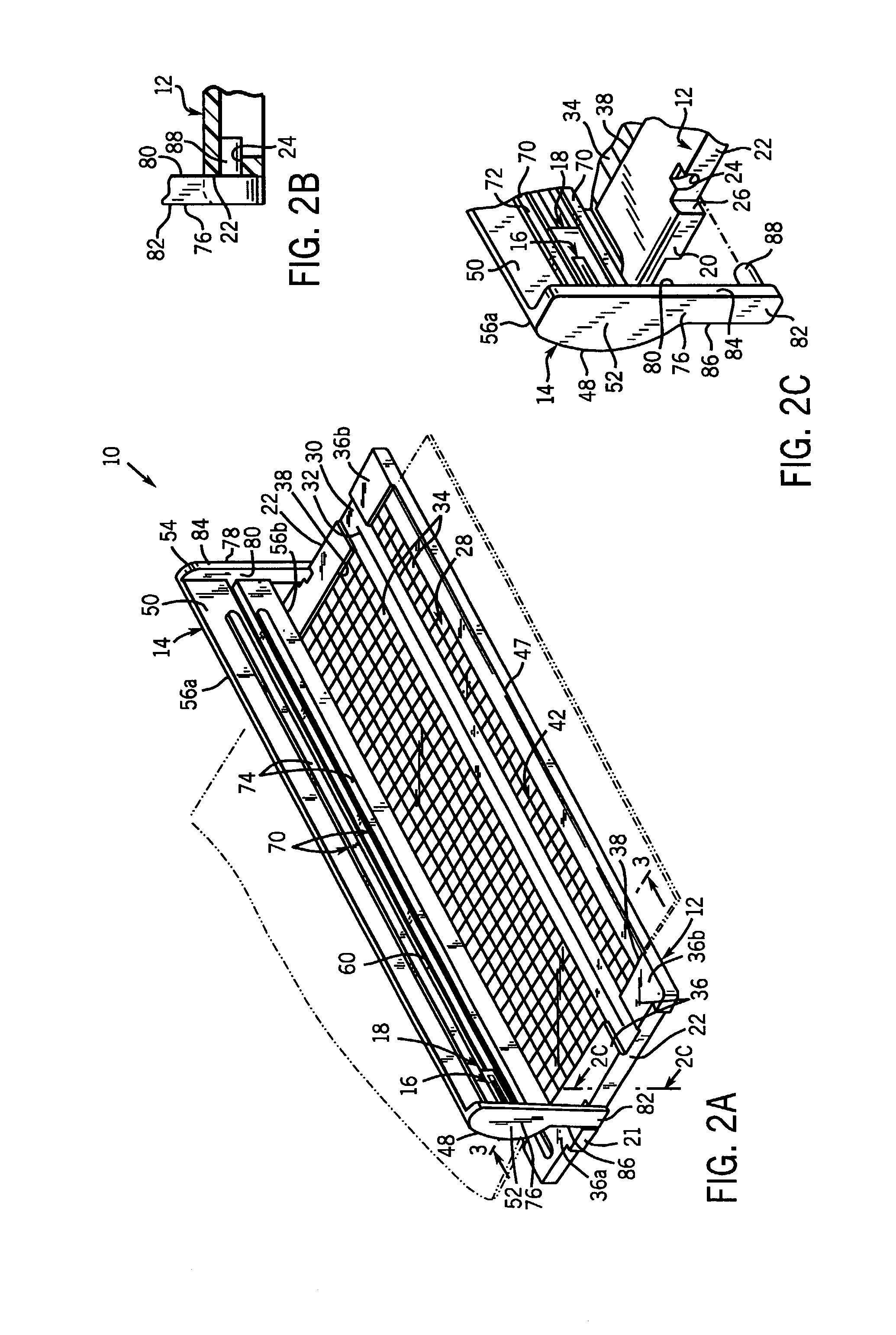
[0031]As shown in FIGS. 1–3 the base 12 includes a first side 20 and a second side 21, the first side 20 and the second side 21 each include a recess 22 having an aperture 24. Each recess 22 has a wall 26 near the aperture 24.

[0032]The base 12 also includes a top surface 28 having a cutting region 30 provided with a channel 32 extending substantially the entire distance between the first side 20 and the second side 21. The top surface 28 also includes a support surface 34. A pair of raised guides 36 are integrally formed with top surface 28 and are located near the first side 20 and the second side 21. Each raised guide 36 includes a guide wall 38 normal to the top s...


PUM

PropertyMeasurementUnit
widthaaaaaaaaaa
widthaaaaaaaaaa
anglesaaaaaaaaaa

Abstract

A material trimmer including a base having a support surface and a cutting region having a channel. A plate is movably attached to the base and includes oppositely facing upper and lower surfaces, an elongated slot therethrough, an elevated portion proximate each side of the slot, and a distal second end with the elevated portion leading to an arcuate surface. A carrier includes a top flange having a pair of oppositely extending sides and a foot extending from the top flange. The foot is slidably received within the slot, and a portion of the pair of oppositely extending sides are arcuate in shape and slidably received within the arcuate surface of the elevated portion. A blade is attached to the carrier, a portion of which extends below the lower surface of the plate within the channel when the plate is disposed over the cutting region.

Description

FIELD OF THE INVENTION[0001]The present invention is directed to paper trimmers. More particularly, the present invention is related to a paper trimmer including a mechanism for cutting materials along a substantially straight line.BACKGROUND OF THE INVENTION[0002]Devices for cutting or trimming sheet material utilizing different types of cutting blades are well known in the art. For example, early sheet cutting devices and mechanisms were found in industrial situations in which large rolls of sheet material needed to be cut. Different types of cutters or trimmers have been adapted for office or personal use.[0003]Conventional paper cutters often include an elongated blade pivotally attached to a cutting board at one end. In these “guillotine-type” cutters, the elongated blade is lowered about the pivot, thereby cutting a paper or material by shearing action. The elongated blade is often exposed, posing a significant danger, especially for use by children. Another drawback of this t...

Claims


Application Information

Patent Timeline
Patent Type & Authority Patents(United States)
IPC IPC(8): B26D7/02B26D1/04B23D35/00B26D7/01
CPCB23D35/008B26D7/015B26D1/045B26D2007/0087Y10T83/7763Y10T83/8749Y10T83/7507Y10T83/8822
Inventor SCHULZ, WILLIAM J.
Owner ALTERRA HLDG
Learn More