Die casting reciprocator safety bar

a safety bar and reciprocator technology, applied in the direction of mold control devices, manufacturing tools,foundry moulding apparatus, etc., can solve the problems of reducing the productivity of the die casting system and significant time to the casting cycle tim

Active Publication Date: 2007-11-27
PACE IND LLC A DELAWARE CO
View PDF2 Cites 7 Cited by
  • Summary
  • Abstract
  • Description
  • Claims
  • Application Information

AI Technical Summary

Problems solved by technology

However, such an interlock arrangement would add a significant amount of time to the casting cycle time, thereby reducing the productivity of the die casting system.

Method used


Image

  • Die casting reciprocator safety bar
  • Die casting reciprocator safety bar
  • Die casting reciprocator safety bar

Examples


Embodiment Construction

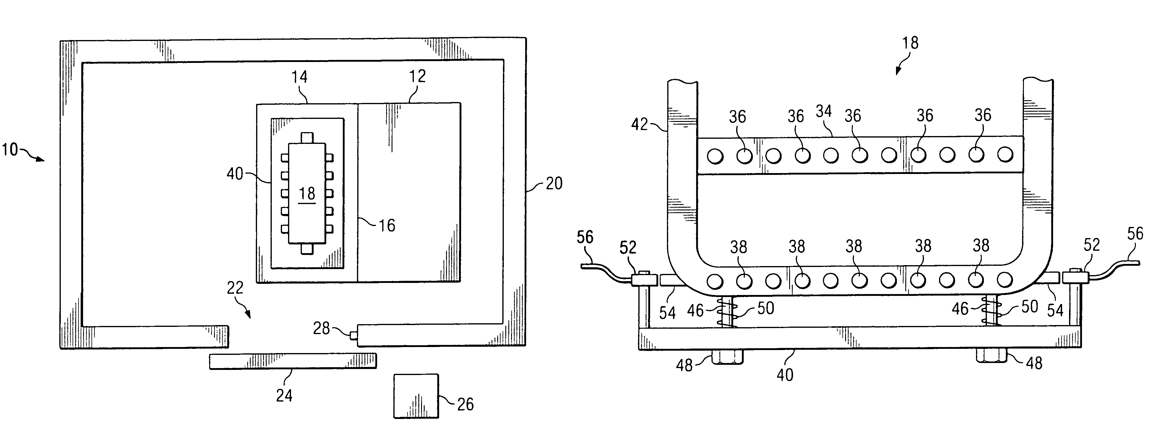
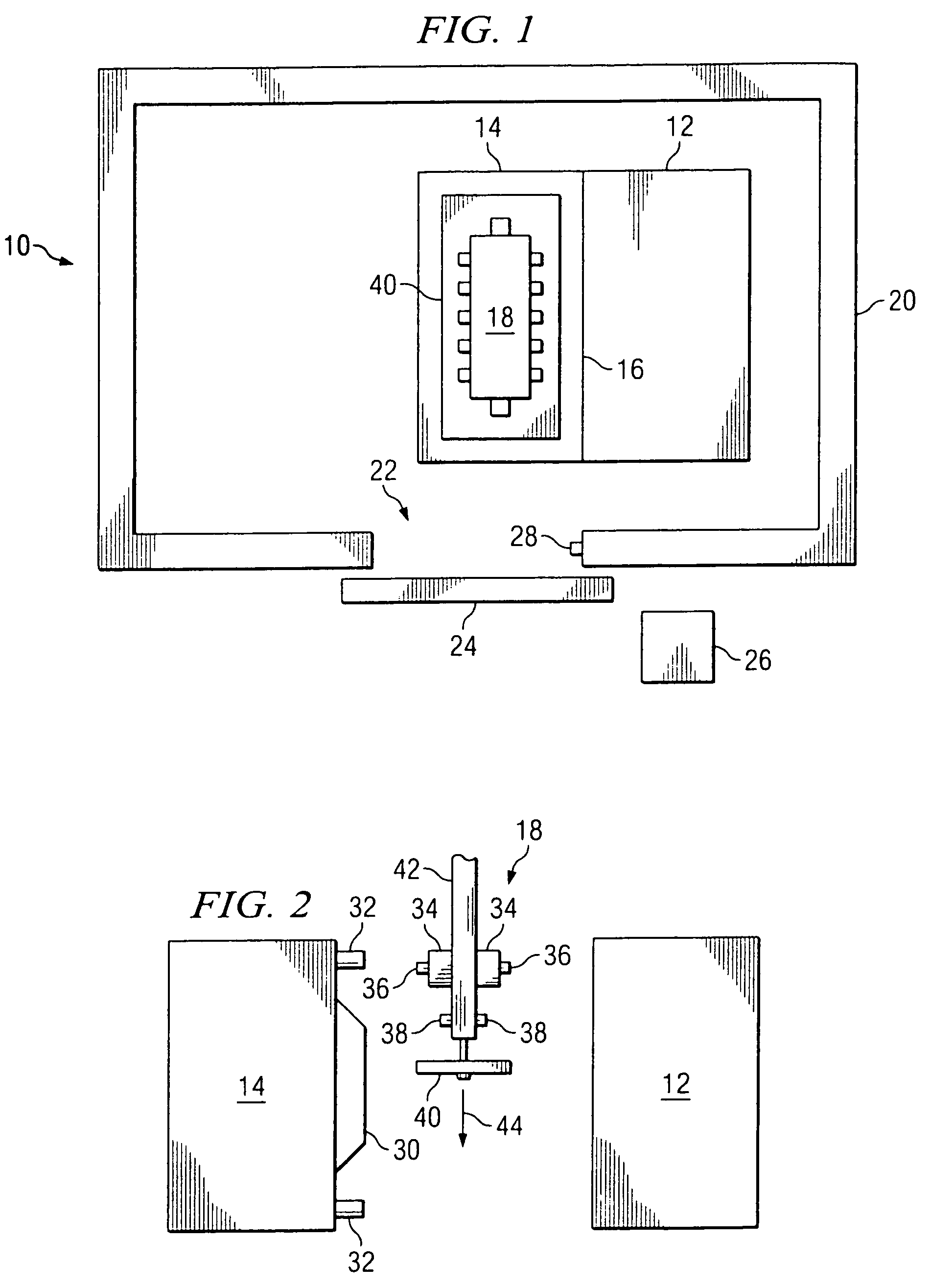
[0012]FIG. 1 is a simplified plan view of a typical die casting system 10 according to the present invention. A stationary or fixed die half 12 and a moveable or injector die half 14 are shown meeting at a parting line 16. Above the fixed die half 12 is shown a reciprocator 18, described in more detail below. The die or mold 12, 14 is surrounded by an enclosure 20 having an entrance 22. A door 24 is provided across entrance 22. A system control panel 26 is typically located near the door 24. A reciprocator activating switch or button 28 may be provided on the enclosure 20, just inside the door 24.

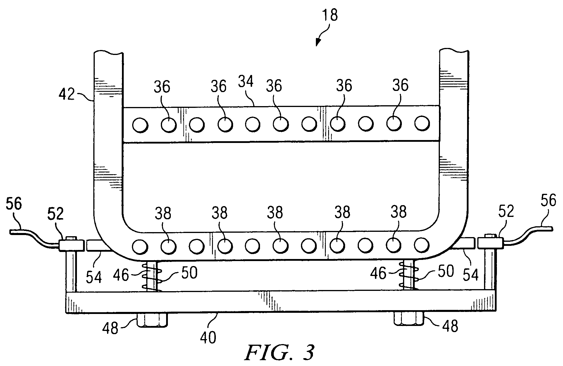
[0013]FIG. 2 is an elevation view of the mold 12, 14 shown in its open position with the reciprocator 18 beginning its operating cycle. A die face 30 of moveable die half 14 is visible in FIG. 2. Guide pins 32 are provided to insure proper alignment of the mold 12, 14, when the pins 32 engage corresponding holes in the fixed die half 12. The reciprocator 18 includes a lubricant sprayer 34 w...


PUM

PropertyMeasurementUnit
pressuresaaaaaaaaaa
cycle timeaaaaaaaaaa
distanceaaaaaaaaaa

Abstract

An automated reciprocator for applying lubricant to the cavity of a die casting system having a safety bar for preventing the reciprocator from injuring a person or damaging equipment which may be present in the reciprocator travel path. The safety bar is movably carried on the lower side of the reciprocator and includes a sensor to detect relative movement between the safety bar and the reciprocator. The proximity sensor is coupled to a control system. If the safety bar contacts an object as the reciprocator is moving down, the sensor signals the control system and the reciprocator is stopped.

Description

CROSS-REFERENCE TO RELATED APPLICATIONS[0001]None.STATEMENT REGARDING FEDERALLY SPONSORED RESEARCH OR DEVELOPMENT[0002]Not applicable.REFERENCE TO A MICROFICHE APPENDIX[0003]Not applicable.FIELD OF THE INVENTION[0004]The present invention relates to automated die casting systems having reciprocating spray systems, and more particularly to a reciprocating spray system including a safety bar preventing the reciprocator from injuring an operator of the die casting system.BACKGROUND OF THE INVENTION[0005]Die casting is a manufacturing process for producing accurately dimensioned, sharply defined, smooth or textured-surface metal parts. A steel mold capable of producing tens of thousands of castings in rapid succession is made in at least two sections to permit removal of castings. These sections are mounted securely in a machine and are arranged so that one is stationary (fixed die half) while the other is moveable (injector die half). To begin the casting cycle, the die cavity is coate...

Claims


Application Information

Patent Timeline
Patent Type & Authority Patents(United States)
IPC IPC(8): B22D17/32
CPCB22D17/2007B22D17/32B22D17/2092
Inventor THOMASON, DAVID R.BUMPUS, DAVID E.ALFORD, DANNY S.MARSHALL, OLEN L.
Owner PACE IND LLC A DELAWARE CO
Why Eureka
Try Eureka