Combined mouth expanding and saliva ejecting dental apparatus

a dental apparatus and saliva technology, applied in the field of dental procedures, can solve the problems of relatively complex devices in construction and use, devices that lack simplicity in design, manufacture and function, and achieve the effect of improving visualization

Inactive Publication Date: 2007-11-27
PATRICKUS JOHN E
View PDF21 Cites 28 Cited by
  • Summary
  • Abstract
  • Description
  • Claims
  • Application Information

AI Technical Summary

Benefits of technology

[0006]The combined retractor and saliva ejector apparatus of the present invention has obtained these objects. It provides for a combined mouth retracting and saliva ejecting device having a forward suction portion, a right cheek retractor portion, a left cheek retractor portion, and a rearward suction portion. The device is functionally adapted and configured to be placed within the mouth of a dental patient. In the preferred embodiment, the device is constructed of a single piece of rigid, but resilient, tubular material, the material having an elastomeric memory. Although preferably cylindrical, it is to be understood that any tubular material, including a tubular material having an oblate or other cross section, could be used without deviating from the scope of this invention. The device can be constructed of material so as to be either disposable or nondisposable, the nondisposable version being capable of heat or chemical sterilization. The device can be made in almost any size to accommodate the wide variety of patients that it may be used with, including children. In an alternative embodiment, the device incorporates fiber optic technology whereby light transmissive fibers are imbedded into the device to allow for selective illumination within the patient's mouth as either a light source for light curable dental compounds or for enhanced visualization.

Problems solved by technology

In the experience of this inventor, such devices have a tendency to be relatively complex in construction and in use.
But again, such devices tend to lack simplicity in design, in manufacture and in functionality.

Method used


Image

  • Combined mouth expanding and saliva ejecting dental apparatus
  • Combined mouth expanding and saliva ejecting dental apparatus
  • Combined mouth expanding and saliva ejecting dental apparatus

Examples


Embodiment Construction

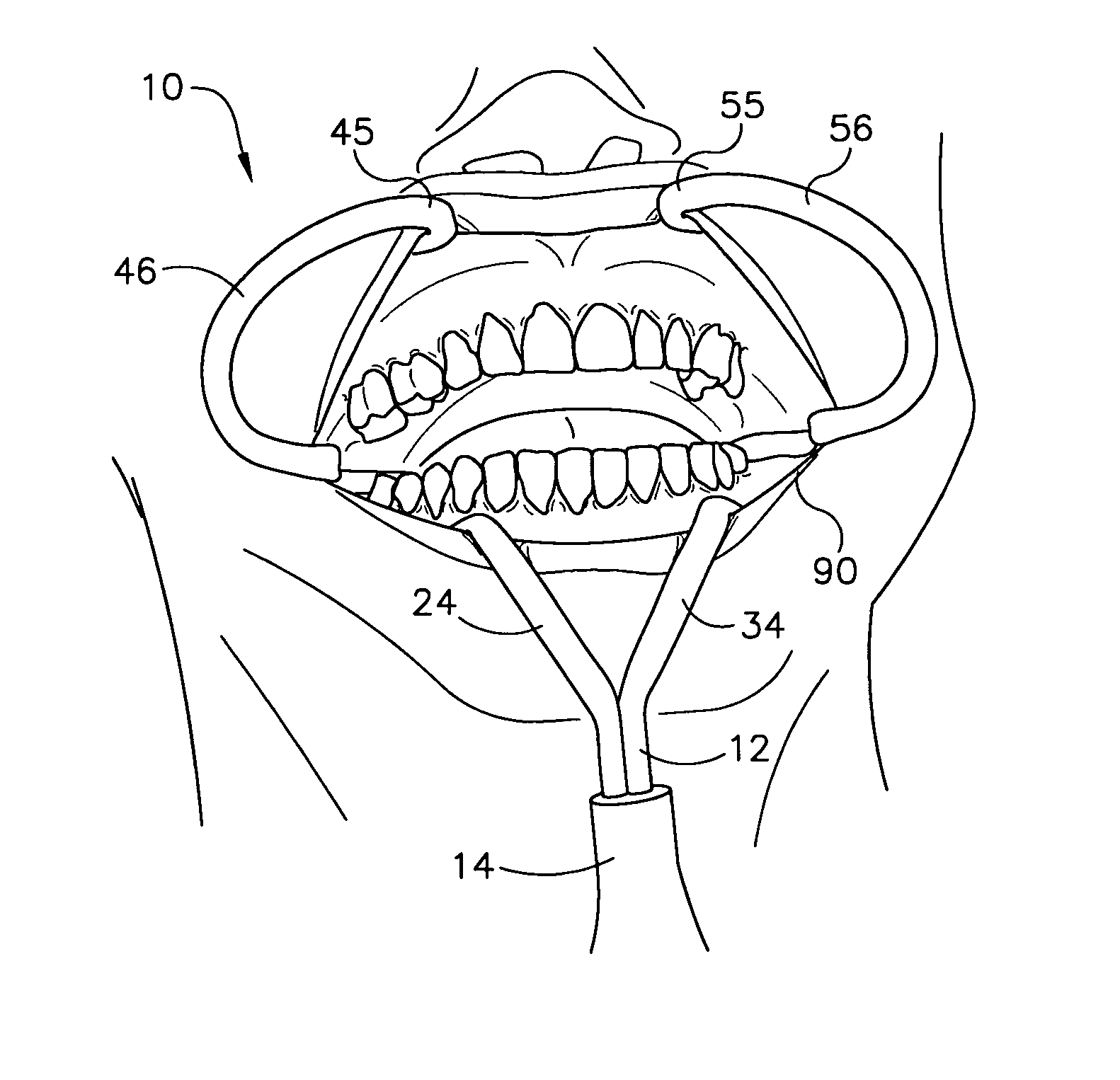
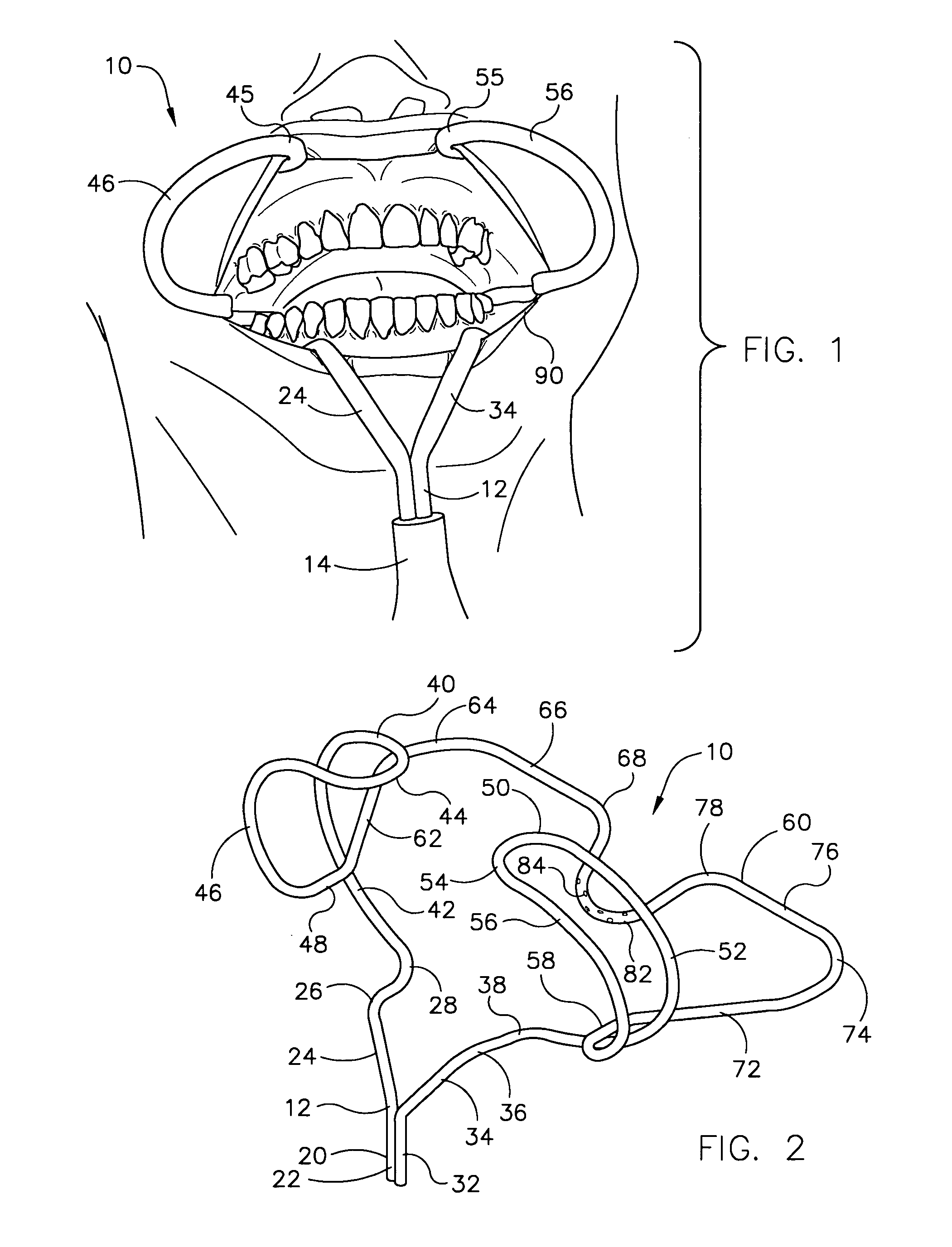
[0013]Referring now to the drawings in detail wherein like numbers represent like elements throughout, FIG. 1 illustrates a perspective view of one embodiment of the retractor and saliva ejector device, generally identified 10, constructed in accordance with the present invention. As shown, the device 10 includes several major portions. Specifically, the device 10 includes a forward suction portion 20, a right cheek retractor portion 40, a left cheek retractor portion 50, and a rearward suction portion 60. See FIG. 2. Referring again to FIG. 1, it will be seen that the device 10 is functionally adapted and configured to be placed within the mouth 90 of a dental patient. Details of this placement will be discussed later in this detailed description.

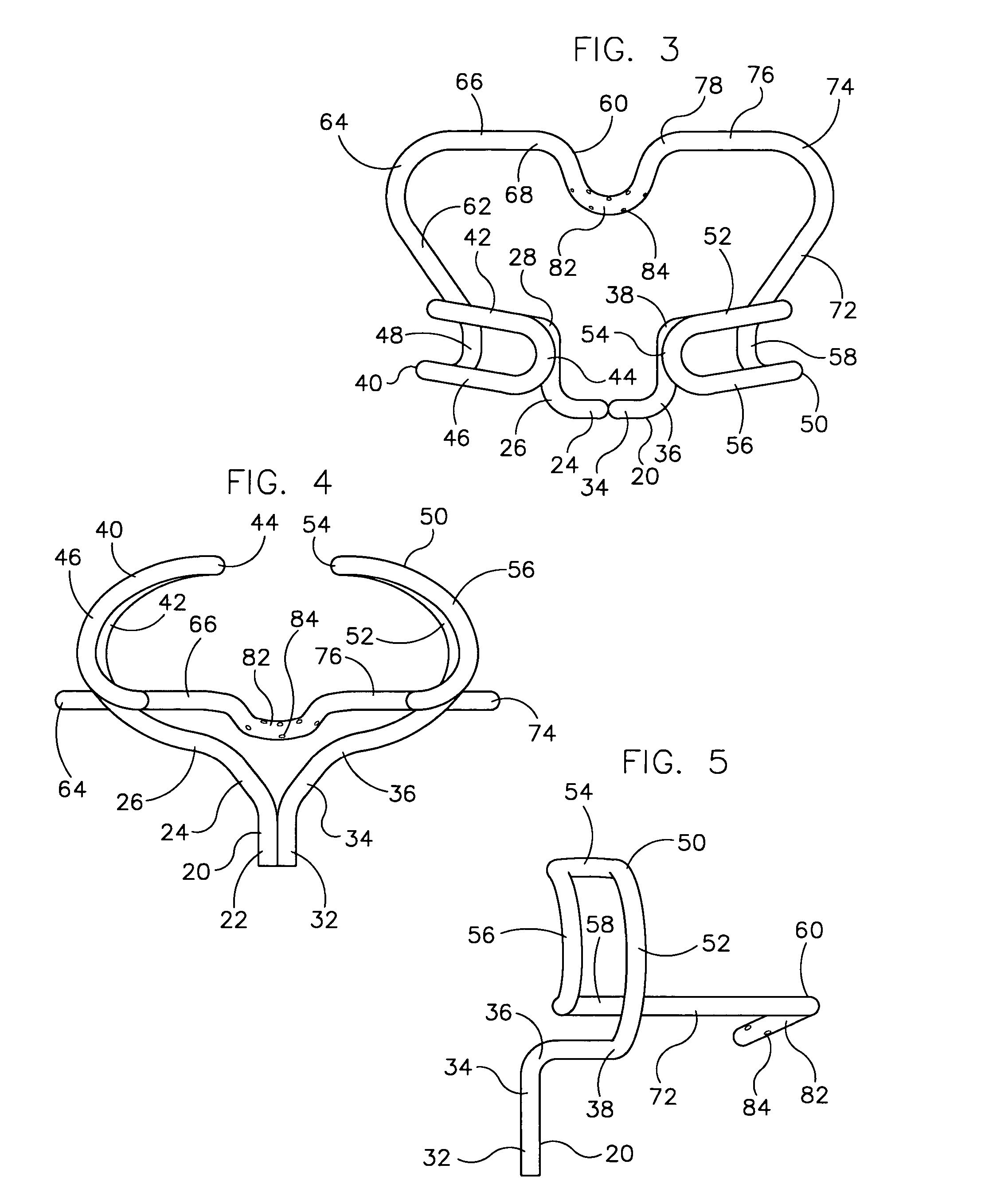
[0014]Referring now to FIG. 2, it will be seen that the device 10 is, in the preferred embodiment, constructed of a single piece of tubular material 12. Although preferably cylindrical, it is to be understood that any tubular material, inc...


PUM


Abstract

A combined mouth retracting and saliva ejecting device has a forward suction portion, a right cheek retractor portion, a left cheek retractor portion, and a rearward suction portion, the device being configured to be placed within the mouth of a dental patient. The device is constructed of a single piece of rigid, but resilient, tubular material, the material having an elastomeric memory. The device is tubular and has a cylindrical or other shape cross section and can be constructed of material so as to be either disposable or nondisposable, the nondisposable version being capable of heat or chemical sterilization. The device can be made in almost any size to accommodate the wide variety of patients that it may be used with, including children. The device may also incorporate fiber optic technology whereby light transmissive fibers are imbedded into the device to allow for selective illumination within the patient's mouth as either a light source for light curable dental compounds or for enhanced visualization.

Description

[0001]This application claims the benefit of U.S. Provisional Patent Application Ser. No. 60 / 560,503, filed Apr. 8, 2004.FIELD OF THE INVENTION[0002]This invention relates generally to dental procedures and to instruments and devices used by professionals during the performance of dental procedures. More particularly, it relates to a combined mouth expanding and saliva ejecting device to provide access to the dentist's working field and to help keep that working field dry during the procedure. In an alternative embodiment, it provides for such a dental device that also incorporates fiber optic technology to direct light into the working field, such light being used for enhanced visualization and for light-curing dental compounds.BACKGROUND OF THE INVENTION[0003]During the performance of various dental procedures, the dentist's continuous visualization of and access to all points within the patient's mouth is absolutely essential. A number of devices have long been used to retract th...

Claims


Application Information

Patent Timeline
Patent Type & Authority Patents(United States)
IPC IPC(8): A61B1/32A61C17/06
CPCA61C17/043A61C17/08A61C17/10
Inventor PATRICKUS, JOHN E.
Owner PATRICKUS JOHN E
Why Eureka
Try Eureka