Methods and systems for position sensing of components in a manufacturing operation

a technology for manufacturing operations and components, applied in the field of methods, can solve the problems of not providing optimal position and orientation data for the tool or the component, and it is difficult and expensive to place all the receivers on the component or the tool, so as to reduce the overall cost and complexity of gathering position, and increase the fidelity of position data

Inactive Publication Date: 2007-12-04
THE BOEING CO
View PDF22 Cites 33 Cited by
  • Summary
  • Abstract
  • Description
  • Claims
  • Application Information

AI Technical Summary

Benefits of technology

[0005]The present invention is directed to methods and systems for position sensing during manufacturing operations. Embodiments of methods and systems in accordance with the present invention may advantageously increase position data fidelity while also providing orientation data. Moreover, embodiments of methods and systems in accordance with the present invention may also decrease the overall cost and complexity of gathering position and orientation data by decreasing the number of necessary fixed transmitters used by a positioning system.

Problems solved by technology

While GPS uses satellites orbiting the earth to determine positioning information, IRGPS employs infrared laser transmitters emitting infrared pulses from known, fixed positions throughout a relatively limited manufacturing area.
For example, due to the curved nature of components, as well as congestion of the work space arising from lifts, cranes and other tools inherent in manufacturing, it can be difficult and expensive to place all of the required receivers on a component or a tool in the line of sight of at least two transmitters.
Moreover, even when this requisite can be satisfied, the positioning system may still not provide optimal position and orientation data for the tool or the component.

Method used


Image

  • Methods and systems for position sensing of components in a manufacturing operation
  • Methods and systems for position sensing of components in a manufacturing operation
  • Methods and systems for position sensing of components in a manufacturing operation

Examples


Embodiment Construction

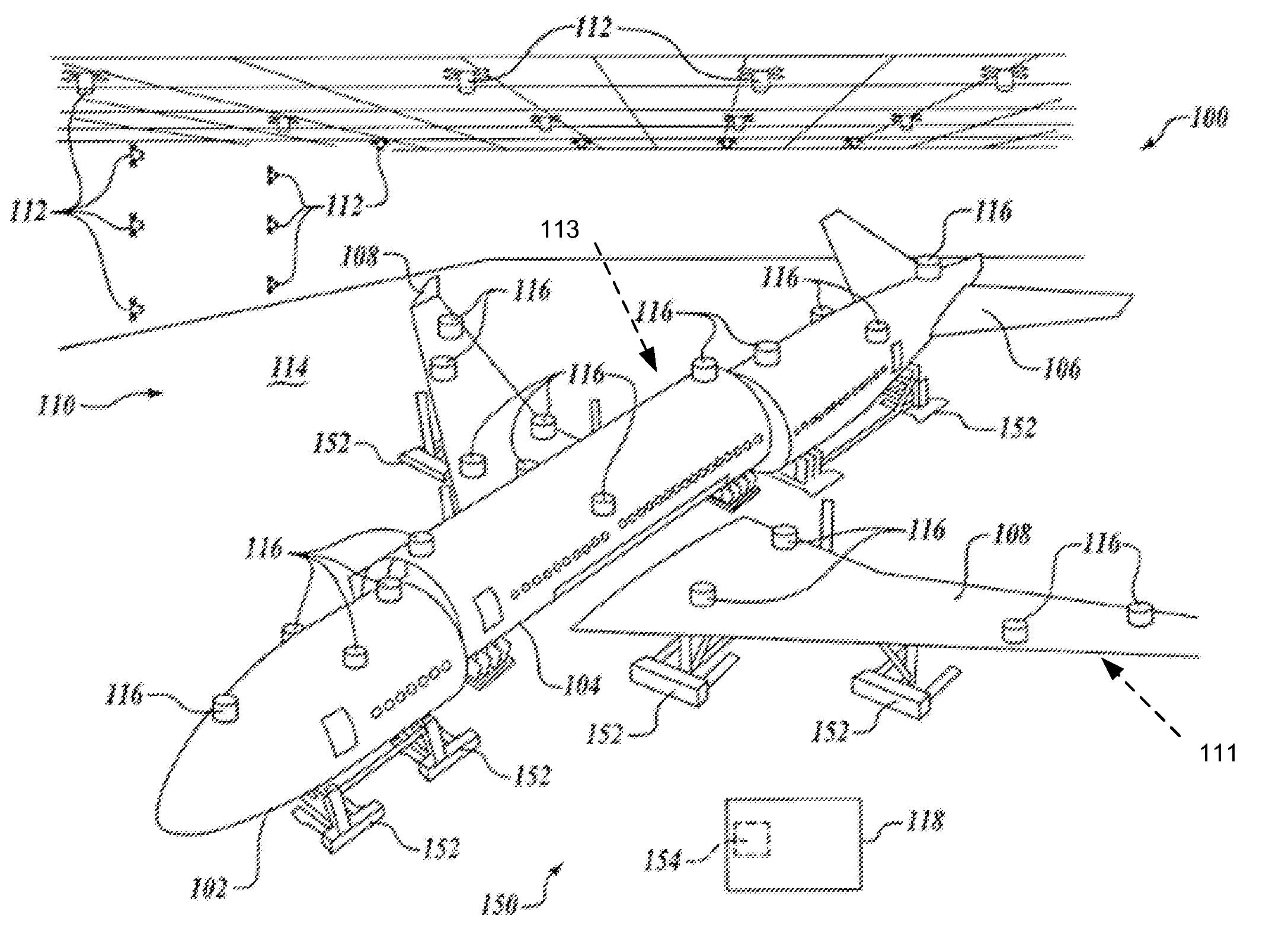
[0016]The present invention relates to methods and systems for performing position measurements during manufacturing operations. Many specific details of certain embodiments of the invention are set forth in the following description and in FIGS. 1-7 to provide a thorough understanding of such embodiments. One skilled in the art, however, will understand that the present invention may have additional embodiments, and that the present invention may be practiced without one or more of the details described in the following description.

[0017]Generally speaking, embodiments of methods and systems in accordance with the present invention may advantageously increase position data fidelity during manufacturing operations. Moreover, embodiments of methods and systems in accordance with the present invention may decrease the overall cost and complexity of gathering position data by decreasing the number of necessary fixed transmitters used by a positioning system.

[0018]In one embodiment, a m...


PUM


Abstract

Methods and systems for position sensing are disclosed. In one embodiment, a method includes measuring at least three discrete point positions associated with a first component by using at least one transmitter having a known position and orientation and in a line of sight with the three discrete point positions, the three discrete point positions having known distances relative to one another. The method computes a current position and orientation of the first component using data provided by the at least one transmitter and the three discrete point positions, along with position and orientation data from a last known location of the first component assuming that no sudden position changes since the first component has moved from the last known location. The first and second components may be a workpiece and a tool that performs a manufacturing operation on the workpiece.

Description

FIELD OF THE INVENTION[0001]The present disclosure relates to methods and systems for performing position measurements during manufacturing operations.BACKGROUND OF THE INVENTION[0002]During manufacturing operations, it may be desirable to actively monitor and adjust a position of a tool that performs manufacturing operations on a component in order to ensure the accuracy of the manufacturing operation. Similarly, during the assembly of two components, it may be desirable to actively monitor the positions of the components to ensure an accurate fit. For example, aircraft components may be assembled in relatively expansive manufacturing areas. To achieve a precise fit of the components being assembled, the positions of the tools that perform operations on the components, as well as the locations of the components, may be monitored using position monitoring systems. As tools and components are moved relative to one another, reference points associated with the tools and components may...

Claims


Application Information

Patent Timeline
Patent Type & Authority Patents(United States)
IPC IPC(8): G06F19/00G05B19/18
CPCG01S5/163
Inventor FREEMAN, PHILIP L.DWORSCHAK, JOHN R.MARSH, JOSEPH C.
Owner THE BOEING CO
Why Eureka
Try Eureka