Linear guide apparatus

a guide apparatus and line-shaped technology, applied in the direction of bearings, bearings, shafts and bearings, etc., can solve the problems of increasing the number of parts, increasing the cost of operation, and increasing the complexity of integration, so as to reduce the vibration of driving and improve the acoustic characteristi

Active Publication Date: 2007-12-11
NSK LTD
View PDF16 Cites 14 Cited by
  • Summary
  • Abstract
  • Description
  • Claims
  • Application Information

AI Technical Summary

Benefits of technology

[0024]The present invention has been carried out in order to resolve the problem of the related art and it is an object thereof to provide a linear guide apparatus in which an outer side portion in a width direction of a slider is formed by a mold member for restraining vibration in driving to be low and improving an acoustic characteristic. The mold member made of a synthetic resin is different from that of a block member made of a metal.
[0038]the return passage has a portion for enhancing a lubricating state of the rolling elements.

Problems solved by technology

Although according to the linear guide apparatus of the related art, the return passage 21b is formed by boring the main body 11 made of a metal, the operation takes time, labor and cost.
However, according to the method described in the JP-UM-A-61-85716, a number of parts are increased and integration is complicated more than the method of boring the main body made of a metal.
Further, when the closing member is insufficiently fixed, there is a case in which the part is vibrated and noise is emitted.
Therefore, it is difficult to modify the slider after molding.
Further, because a structure of a die of integral molding is complicated, there is a room for improvement also in view of productivity.
That is, according to the slider described in JP-A-7-317762, because the resin continuously covers the slider, modifications including a modification of a groove depth, a shape or the like of the rolling groove cannot be carried out at all after molding.
Therefore, the resin must be destructed when adjustment of pre-pressure is required or an improvement in operability is required.
Further, the resin flows in a thin-walled state at a surrounding the slider, particularly, because the resin is made to flow elongated along the longitudinal direction to the slider, the molding performance is poor and a structure of the die becomes complicated.
Further, a step of cooling the slider after molding by putting the slider into the die is needed and therefore, time is taken for fabrication.
However, because the members are not connected firmly relative to the members which are made of undivided member, it tends to occur vibration when the rolling elements roll in the circulation passage.
However, because the return passage and the direction changing passage are not connected firmly relative to the members which are made of undivided member, it tends to occur vibration when the rolling element rolls between the return passage and the direction changing passage.
Even a small manufacturing error of the snapping means way occur the vibrations.

Method used


Image

  • Linear guide apparatus
  • Linear guide apparatus
  • Linear guide apparatus

Examples


first embodiment

[0082]the present invention will be explained as follows.

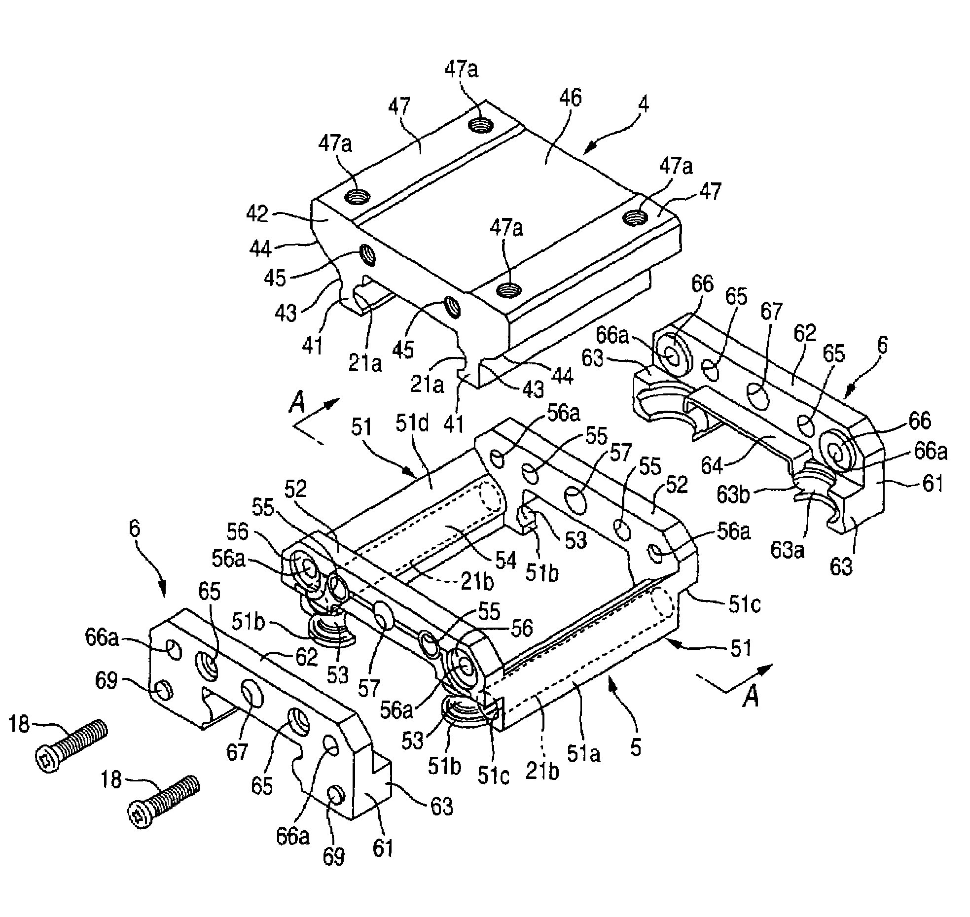
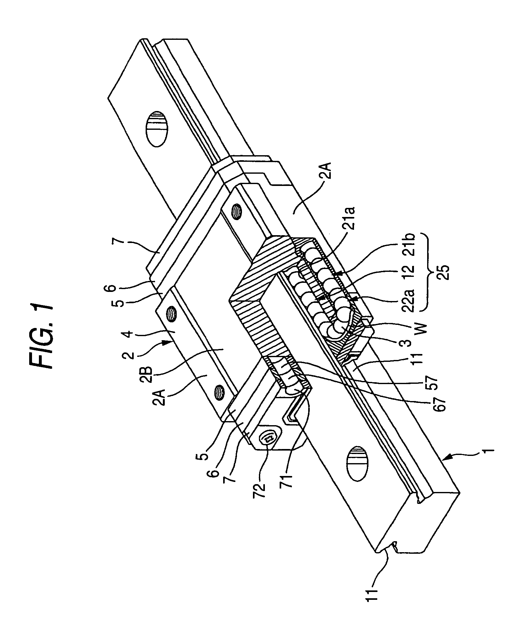
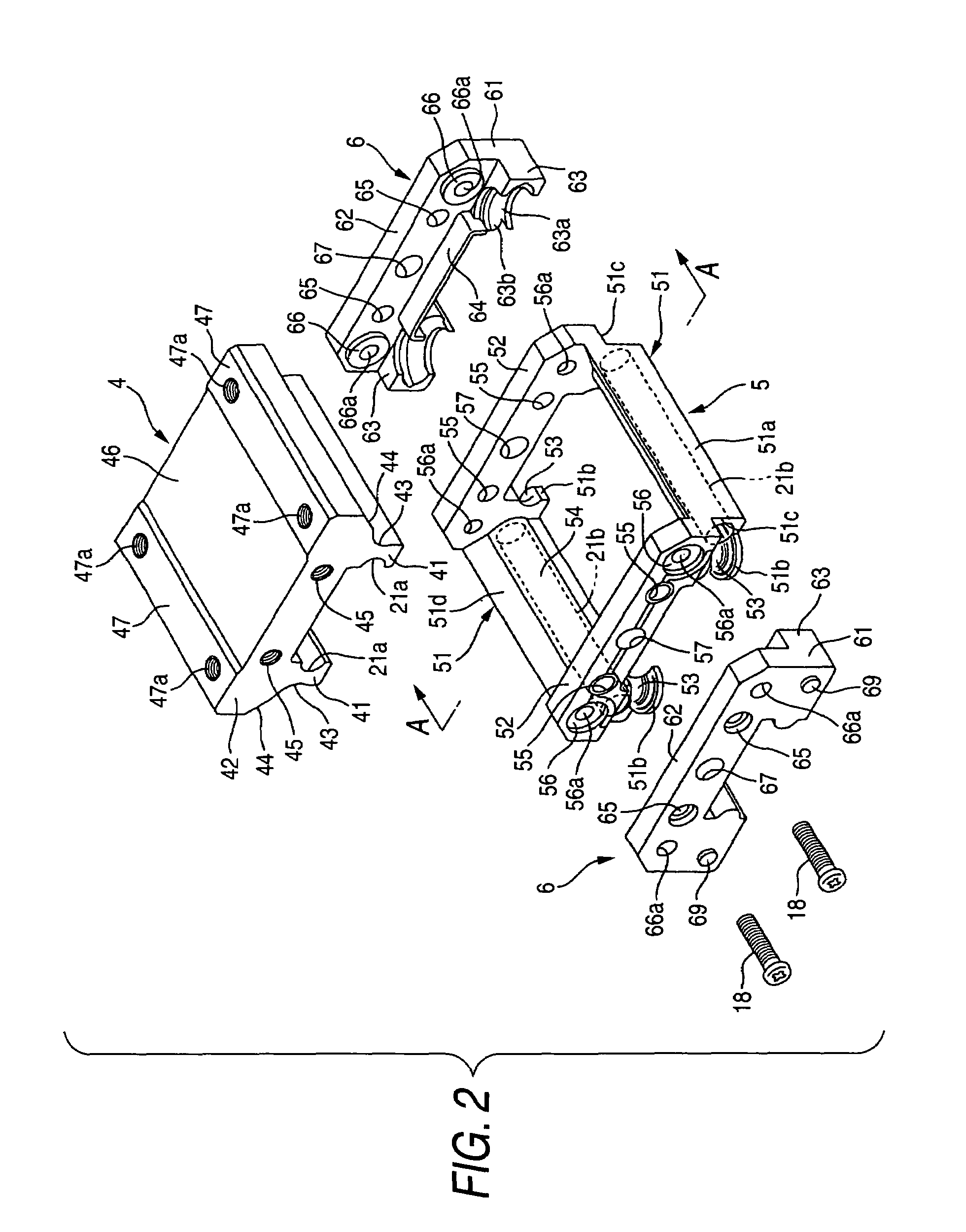
[0083]FIG. 1 is a perspective view showing a linear guide apparatus in correspondence with an embodiment of the present invention. The linear guide is constituted by a guide rail 1, a slider 2 and a plurality of balls 3 as rolling elements.

[0084]The guide rail 1 includes rolling grooves 11 extended in parallel with a longitudinal direction at both side faces thereof. The slider 2 comprises leg portions 2A arranged on both sides in a width direction of the guide rail 1 and a horizontal portion 2B connecting the two leg portions 2A. The horizontal portion 2B is arranged on one end side in a thickness direction of the guide rail 1, which is upper face side of the guide rail 1 in the drawing. Further, both inner side faces of the slider 2 are arranged to be opposed to both side faces of the guide rail 1.

[0085]Inner side faces of the two leg portions 2A of the slider 2 are formed with rolling grooves 21a opposed to the rolling groo...

second embodiment

[0140]the present invention will be explained as follows.

[0141]FIG. 8 is a perspective view showing a linear guide apparatus in correspondence with an embodiment of the present invention. The linear guide is constituted by a guide rail 1001, a slider 1002 and a plurality of balls 1003.

[0142]The guide rail 1001 includes rolling grooves 1011 extended in parallel with a longitudinal direction at both side faces thereof. The slider 1002 comprises leg portions 102A arranged on both sides in a width direction of the guide rail 1001 and a horizontal portion 102B connecting the two leg portions 102A. The horizontal portion 102B is arranged on one end side in a thickness direction of the guide rail 1001 i.e., upper face side of the guide rail 1001 in FIG. 8. Further, both inner side faces of the slider 1002 are arranged to be opposed to both side faces of the guide rail 1001.

[0143]Inner side faces of the two leg portions 102A of the slider 1002 are formed with rolling grooves 1021a opposed t...


PUM


Abstract

A slider is constituted by a main body made of a metal and a frame member and an end cap made of a synthetic resin. The main body is provided with a rolling groove. The frame member is provided with a return passage and an inner side groove of a direction changing passage. The end cap is provided with an outer side groove of the direction changing passage. A longest outer dimension in a slider width direction between lower end portions of inner legs of the main body is made to be larger than a shortest dimension in the slider width direction between projected portions of the frame member. The frame member is detachably engaged with the main body by putting a side of a leg portion of the main body to and from a side of a frame member horizontal portion by elastically deforming the frame member.

Description

BACKGROUND OF THE INVENTION[0001]1. Field of the Invention[0002]The present invention relates to a linear guide apparatus constituted by a guide rail, a slider and a plurality of rolling elements.[0003]2. Description of the Related Art[0004]FIG. 7 shows a example of the linear guide apparatus according to the related art. As shown in the drawing, a linear guide apparatus is constituted by a guide rail 1, a slider 2, which is also referred to as “bearing”, and a plurality of ball 3 as a rolling element.[0005]The guide rail 1 includes rolling grooves 11 extended in axial direction and formed at both side surfaces thereof. The slider 2 has leg portions 2A arranged on both sides in a width direction of the guide rail 1, and a horizontal portion 2B connecting the leg portions 2A each other. The horizontal portion 2B is arranged on one end side (i.e., upper face side of the guide rail 1 in the drawing) in a thickness direction of the guide rail 1, that is a direction orthogonal to both of...

Claims


Application Information

Patent Timeline
Patent Type & Authority Patents(United States)
IPC IPC(8): F16C29/06
CPCF16C29/0657F16C29/0602
Inventor YAMAZAKI, YASUYUKIYOSHIDA, TOSHIO
Owner NSK LTD
Why Eureka
Try Eureka