Position sensor and assembly

a technology of positioning sensor and assembly, which is applied in the field of positioning sensor, can solve problems such as limited resolution capability

Active Publication Date: 2007-12-11
GM GLOBAL TECH OPERATIONS LLC +1
View PDF14 Cites 59 Cited by
  • Summary
  • Abstract
  • Description
  • Claims
  • Application Information

AI Technical Summary

Problems solved by technology

This arrangement may have limited resolution capability.

Method used


Image

  • Position sensor and assembly
  • Position sensor and assembly
  • Position sensor and assembly

Examples


Embodiment Construction

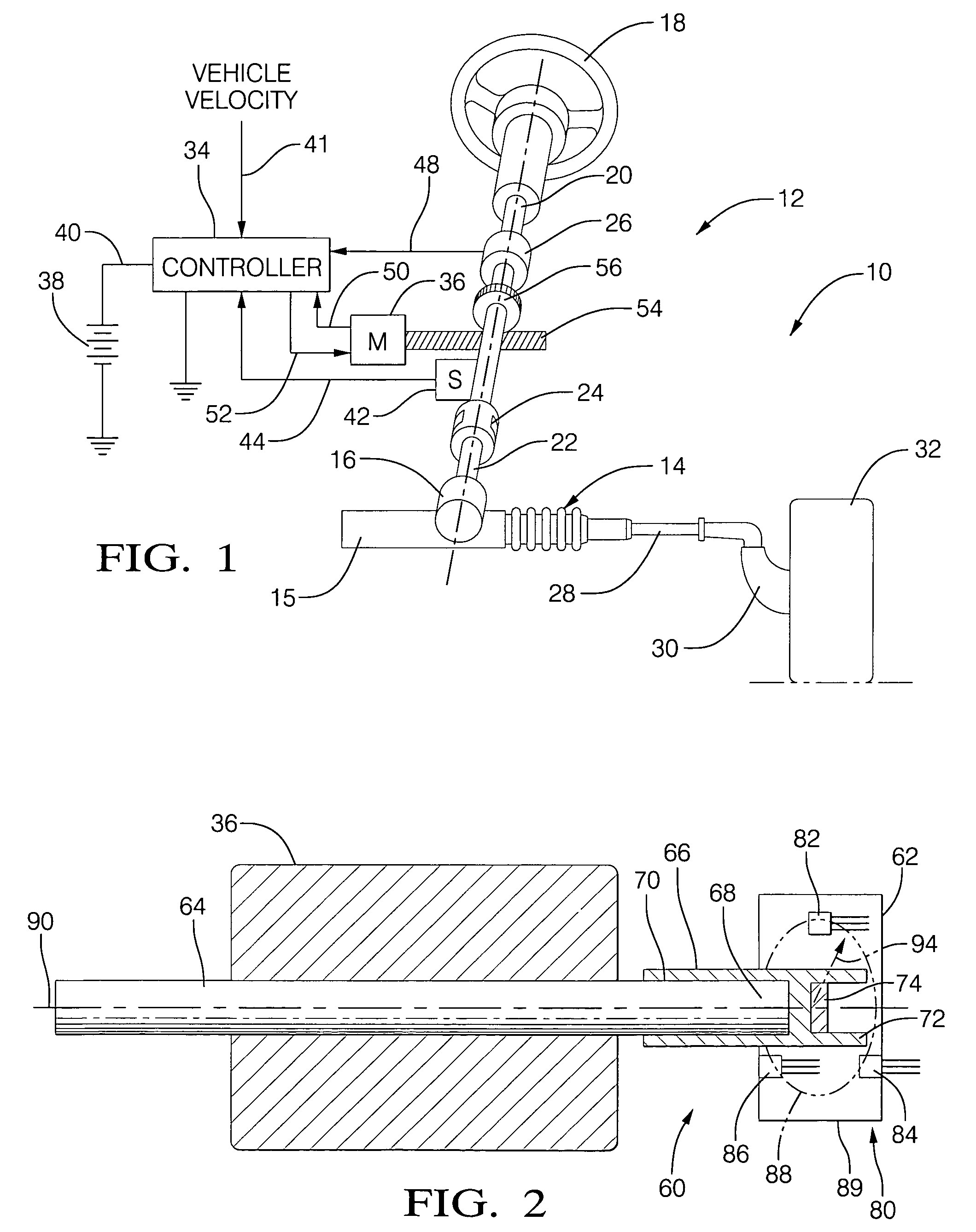
[0025]Referring to FIG. 1, an exemplary system for utilizing the position sensor is shown. While one such system is described herein for incorporating the position sensor, it should be understood that the position sensor disclosed herein may be used in alternate applications, and should not be limited to applications involving motors. As shown in FIG. 1, a motor vehicle 10 may be provided with an electric power steering system 12. Electric power steering system 12 may include a conventional rack and pinion steering mechanism 14 having a toothed rack 15 and a pinion gear (not shown) under a gear housing 16. As steering wheel 18 is turned, an upper steering shaft 20 turns a lower shaft 22 through a universal joint 24. Lower steering shaft 22 turns the pinion gear. The rotation of the pinion gear moves the pinion rack 15, which then moves tie rods 28 (only one shown). In turn, tie rods 28 move steering knuckles 30 (only one shown) to turn wheels 32 (only one shown).

[0026]An electric po...


PUM


Abstract

Disclosed herein, in an exemplary embodiment, is a position sensor assembly including a circular-shaped or rhombus-shaped magnet and at least one magnetic flux density sensor, such as a Hall effect sensor, wherein rotation of the magnet is detected by the at least one sensor. The magnet may be positioned coaxially with the longitudinal axis of a rotor shaft of a motor and provided within a support. A position extraction algorithm may be employed using the output from the sensors to detect the position of the rotor shaft.

Description

BACKGROUND[0001]This invention relates generally to a position sensor, and more particularly, this invention relates to an improved and low-cost high resolution position sensor.[0002]Position sensors with digital outputs provide discrete position information only whereas an analog position sensor can provide both position information and outputs that can be used to drive an electric motor or other similar electromechanical devices. Many of these devices are driven by sinusoidal excitations as a function of position. Consequently, an analog position sensor having an output that varies sinusoidally with position could be used to generate absolute angular positions as, for example, an electrical power steering system to measure the angle of rotation of the steering wheel, and / or reference signals to produce the desired sinusoidal phase drive currents and voltages to drive electric motors and other similar electromechanical devices.[0003]Applications may further include throttle positio...

Claims


Application Information

Patent Timeline
Patent Type & Authority Patents(United States)
IPC IPC(8): G01B7/30G01R33/06H01L43/06H01L43/08
CPCG01D5/145G01D2205/77
Inventor ISLAM, MOHAMMAD S.MIELKE, MATTHEWSEBASTIAN, TOMY
Owner GM GLOBAL TECH OPERATIONS LLC
Why Eureka
Try Eureka