Two Dimensional Position Sensor

a capacitive position and sensor technology, applied in the direction of instruments, electric digital data processing, input/output process of data processing, etc., can solve the problem of becoming impractical to add further groups of x-electrodes

Inactive Publication Date: 2007-12-06
NEODRON LTD
View PDF51 Cites 309 Cited by
  • Summary
  • Abstract
  • Description
  • Claims
  • Application Information

AI Technical Summary

Benefits of technology

[0028]In WO 2005 / 020056 Philipp describes a position sensor having first and second resistive bus-bars spaced apart with an anisotropic conductive area between them (see FIG. 3 thereof). Electric currents induced in the anisotropic conductive area by touch or proximity flow preferentially towards the bus-bars to be sensed by detection circuitry. Because induced currents, for example those induced by drive circuitry, flow preferentially along one direction, pin-cushion distortions in position estimates are largely constrained to this single direction. Such one-dimensional distortions can be corrected for very simply by applying scalar correction factors, thereby avoiding the need for complicated vector correction. This provides a 2D pattern of conductive material for sensing capacitance behind a plastic or glass panel or other dielectric, which can be used as a 2DxT, whether in the format of a touch screen or ‘touch pad’. The conductor can be clear, for example made of indium tin oxide (ITO), to provide a suitable transparent overlay for a display or other backing.
[0029]This approach works well for relatively small screen sizes up to about a 2 inch (50 mm) diagonal suitable for a cellular telephone but performance degrades with larger screens such as needed for some white goods, for example a microwave oven. Moreover, the handshadow effect can cause problems with this design.

Problems solved by technology

However, in reality, the thickness of the electrode feed-throughs to the peripheral edge regions of the sensitive area for external contacting will become thinner and thinner, so at some point it will become impractical to add further groups of x-electrodes as defined by noise considerations and other relevant factors.

Method used


Image

  • Two Dimensional Position Sensor
  • Two Dimensional Position Sensor
  • Two Dimensional Position Sensor

Examples


first embodiment

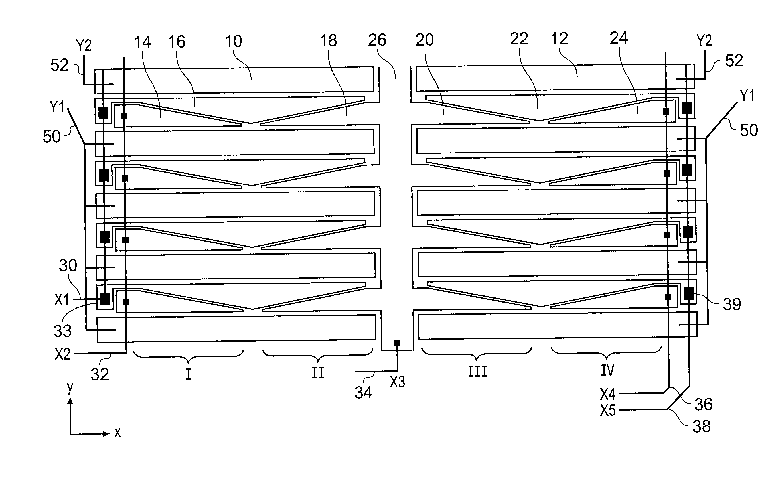
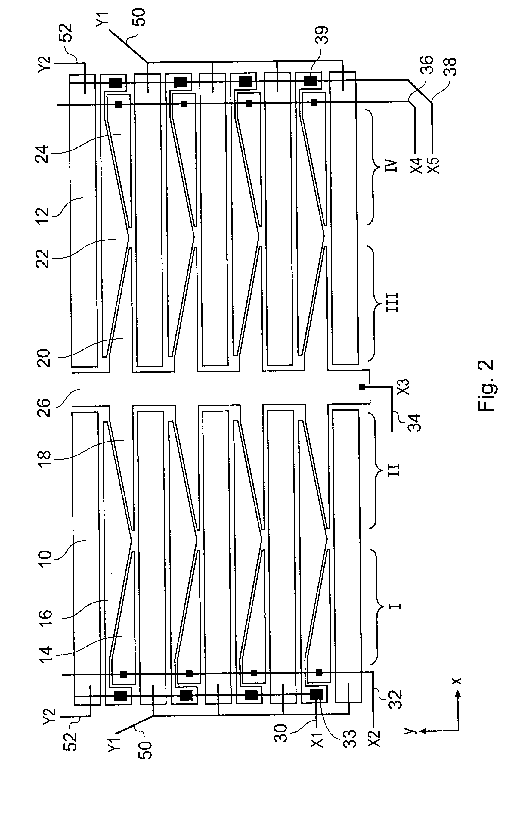
[0069]FIG. 2 is a schematic plan view showing representative parts of an electrode pattern for a 2DCT of a first embodiment, wherein the electrode pattern define a sensitive area for the device. The electrodes are arranged on a substrate which is not expressly shown, but which has an upper surface lying in the plane of the paper. The substrate may conveniently be a flexible transparent plastics material such as polyethylene terephthalate (PET). The substrate will generally be insulating. The electrode pattern is made of indium tin oxide (ITO) having a resistivity of a few hundred ohm / square. This is a transparent material and thus suitable for display applications, or other applications where an underlying button or other template needs to be visible. More generally, the electrode pattern can be made by depositing or removing any suitable conductive material. Deposition can be by vapor deposition or screen printing, for example. Removal can be by laser or chemical etching, for examp...

second embodiment

[0094]In general there must be a minimum of two such external connections in the second embodiment which form end connections of the slider. These end connections should preferably be connected to the top-most and bottom-most y-electrode, or at least ones near the top and bottom. It is also beneficial to provide one or more additional external connections between these two end connections to improve y-position sensing accuracy by effectively forming multiple sliders along the y direction. Usually there will be a desire imposed by cost to limit the number of external connections to a fixed number, in which case as many y-electrode external connections can be provided as there are spare external lines after allocation of sufficient lines for the x-electrodes.

[0095]FIG. 7 is a schematic plan view similar to FIG. 6 showing parts of an electrode pattern and y-connections for a variant of the second embodiment. The y-electrode bars 10 and external connection lines 52′-60′ serve the same f...

fifth embodiment

[0108]FIG. 14 is a schematic plan view showing a part of an electrode pattern for a The pattern here differs from those of the previous embodiments in that the shape of the double-taper x-electrodes 16′ are inverted from a “stork bill” to a “bow tie” shape in which the taper is towards the middle of the double taper instead of away from the middle. This double-taper shape is shown with reference to an embodiment with a spine 26′ although it could also be used in spineless designs. The single taper x-electrodes 14′, 18′ are correspondingly inverted to form the necessary co-extension with the bowtie double taper electrode 16′.

[0109]FIG. 15 is a schematic plan view showing parts of an electrode pattern for a sixth embodiment. This embodiment can be understood by comparison with the first embodiment illustrated in FIG. 2. As in the first embodiment, the sensing area is divided into left and right halves by a central spine 26″. The y-sensing is performed by left and right side y-electro...


PUM


Abstract

A two-dimensional position sensor comprising a substrate with a sensitive area defined by a pattern of electrodes including electrodes for determining x-position and electrodes for determining y-position. The x-electrodes and y-electrodes generally extend in the x-direction and are interleaved in the y-direction. The x-electrodes comprise at least first, second and third groups of elements shaped such that adjacent ones of the elements of the different x-electrode groups co-extend in the x-direction so that the x-electrodes provide ratiometric capacitive signals, thereby providing quasi-continuous x-position sensing across the sensitive area. In addition, the y-electrodes may be resistively connected or arranged in ratiometric pairs to provide quasi-continuous y-position sensing. Alternatively, the x-electrode groups may be interdigitated to form pairs of x-adjacent blocks of differing area to provide stepwise x-position sensing in combination with stepwise y-position sensing provided by the y-electrodes.

Description

BACKGROUND OF THE INVENTION[0001]The invention relates to 2-dimensional capacitive position sensors, typically actuated by a human finger, or a stylus. Example devices include touch screens and touch pads, particularly those over liquid crystal displays (LCDs), or cathode ray tubes (CRTS) and other types of displays, or pen-input tablets, or encoders used in machinery for feedback control purposes. Descriptions of pen or touch input to a machine date back to at least 1908, as embodied in patent DE 203,719.[0002]Touch screens and pointing devices have become increasingly popular and common not only in conjunction with personal computers but also in all manner of other appliances such as personal digital assistants (PDAs), point of sale (POS) terminals, electronic information and ticketing kiosks, kitchen appliances and the like. These devices are evolving continuously into lower priced products and as a result, there is a need for ever lower production cost while maintaining high lev...

Claims


Application Information

Patent Timeline
Patent Type & Authority Applications(United States)
IPC IPC(8): G06F3/041
CPCG01R27/2605G06F3/044G06F3/0443G06F3/0448
Inventor PHILIPP, HARALDHRISTOV, LUBEN
Owner NEODRON LTD
Why Eureka
Try Eureka