
Method and apparatus for displaying a synthesized image viewed from a virtual point of view

a synthesized image and virtual point of view technology, applied in the field of apparatus and a method for displaying a synthesized single image, can solve the problems of inability to understand instantaneously the overall situation, the image from the wide-angle lens does not provide the detail in a specific part, and the apparatus cannot trea

Inactive Publication Date: 2007-12-11
PANASONIC CORP
View PDF24 Cites 311 Cited by
  • Summary
  • Abstract
  • Description
  • Claims
  • Application Information

AI Technical Summary

Problems solved by technology

However, there has been such a problem or the like that a manager needs to consider the continuity between the independently displayed images during the monitoring of the image of each camera in such a prior art apparatus.
Accordingly, it is difficult to understand instantaneously the overall situation of the space shot by the cameras by watching each image.
In addition, in case of synthesizing the respective images into a single image, the apparatus cannot treat, for example, a request by the manager to watch an integrated image viewed from a desired point of view depending on the situation, because the apparatus does not calculate the spatial position of an object shot by the camera.
The same problem occurs in a monitoring apparatus installed on a vehicle.
The image from the wide-angle lens does not provide the detail in a specific part.
However, even if an ordinary lens is replaced by the wide-angle lens, the image of the camera still depends on the position on the body of a vehicle where the camera is installed, and accordingly, it is not possible to obtain a virtual image viewed from a position where the camera is not installed.
However, in the above-mentioned another prior art apparatus for monitoring the surroundings of a vehicle, there has been a problem that it can be difficult to find the correspondence of the obtained synthesized image to the actual object.
However, the cutting-out of the objects outside of the road surface is one of the difficult problems in the field of image recognition, and hence difficult to realize practically.
On the other hand, there is a problem that the shift of the camera during the running causes a shift in the synthesized image.
The problem in this case is, however, that the mechanisms for changing the orientation are necessary to installed in the same number as the number of the cameras, which causes a higher cost.

Method used


Image

  • Method and apparatus for displaying a synthesized image viewed from a virtual point of view
  • Method and apparatus for displaying a synthesized image viewed from a virtual point of view
  • Method and apparatus for displaying a synthesized image viewed from a virtual point of view

Examples


Embodiment Construction

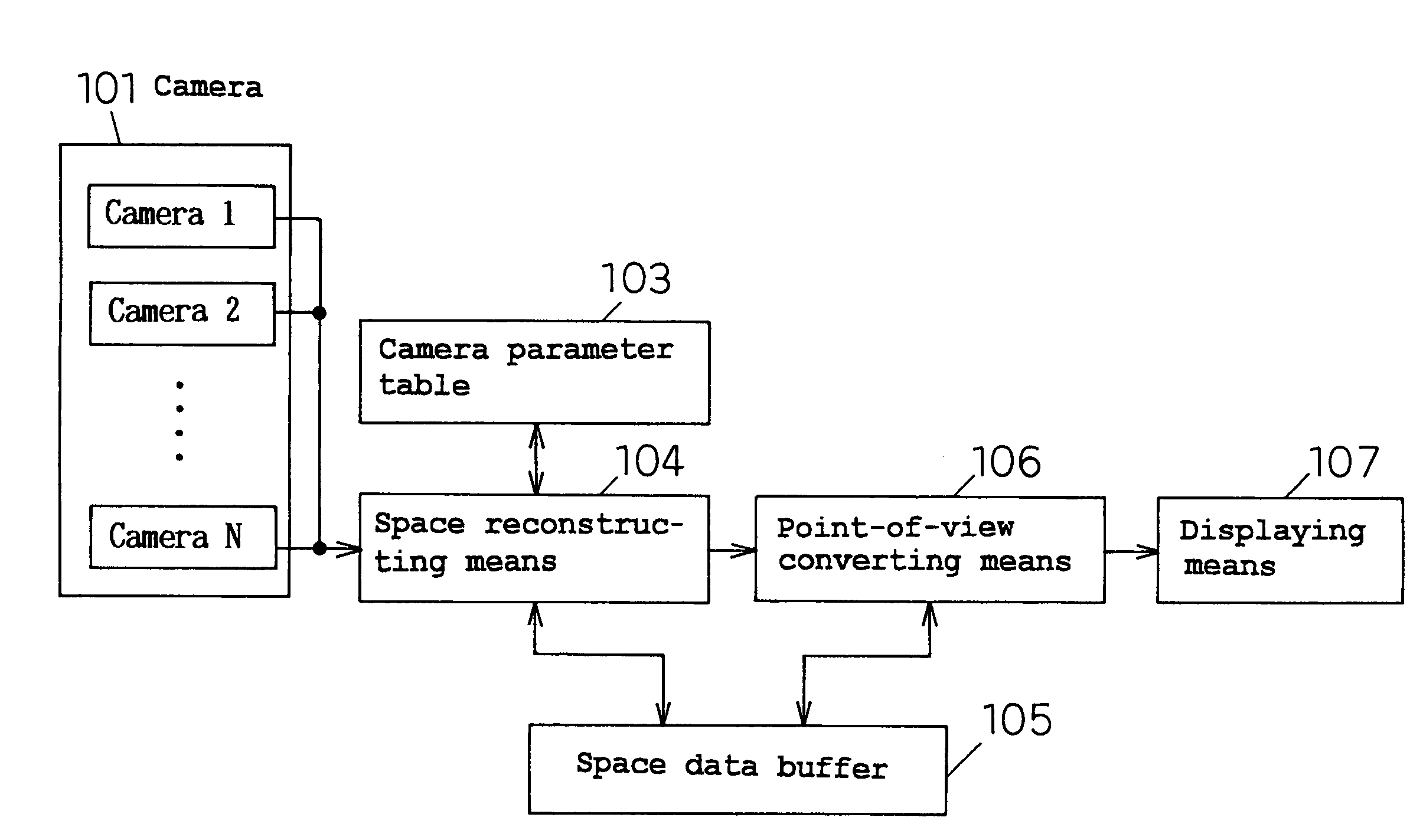
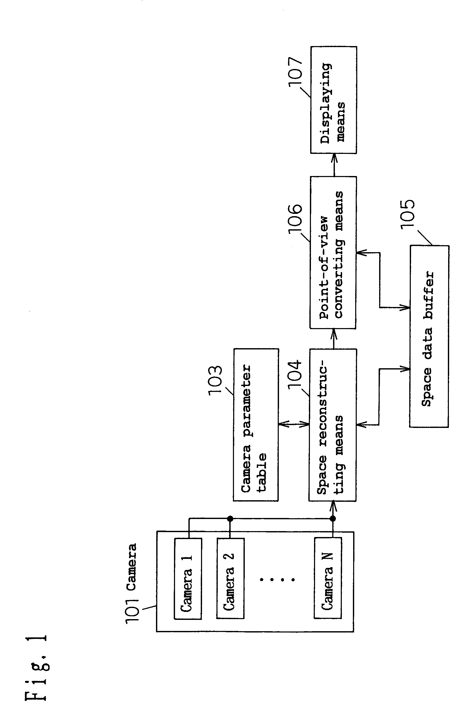
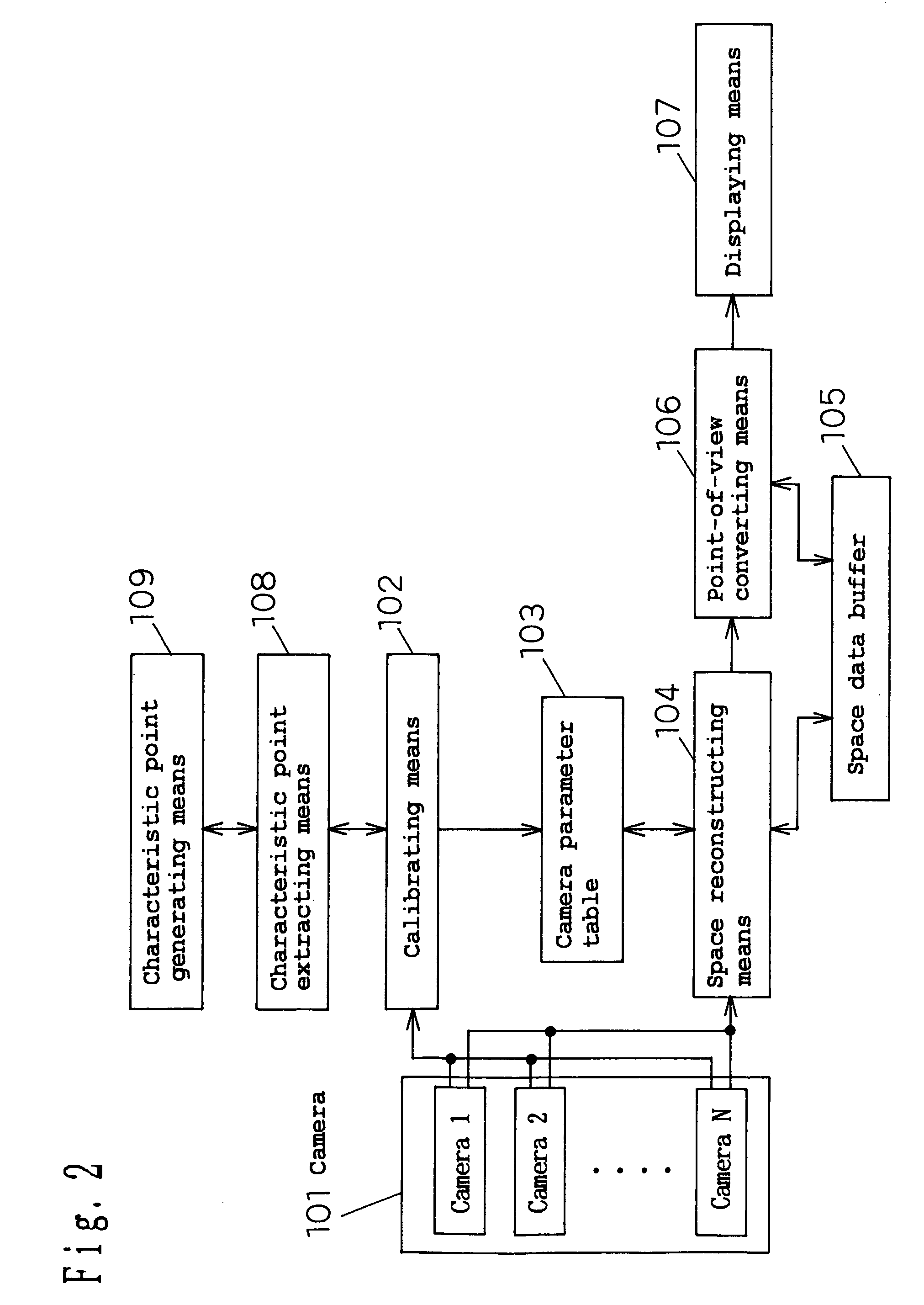
[0190]The basic configuration of the present invention is characterized by comprising: a camera or a plurality of cameras; a camera parameter table for storing the camera parameters indicating the characteristics of said camera or cameras; space reconstructing means of mapping the image input from said camera, into a space model of three-dimensional space depending on said camera parameters thereby generating space data; a space data buffer for temporarily storing the space data generated by said space reconstructing means; point-of-view converting means of synthesizing an image viewed from an arbitrary point of view by referencing to said space data; and displaying means of displaying the image converted by said point-of-view converting means.

[0191]A first application configuration of an image generating apparatus in accordance with the present invention is characterized by comprising calibrating means for obtaining the camera parameters indicating the camera characteristics by an ...


PUM


Abstract

An image generating apparatus comprising: a camera or a plurality of cameras; space reconstructing means for mapping the input image from said camera, into a predetermined space model of a predetermined three-dimensional space; point-of-view converting means of synthesizing an image viewed from an arbitrary virtual point of view in said predetermined three-dimensional space by referencing to said space data mapped by said space reconstructing means; and displaying means of displaying the image converted by said point-of-view converting means.

Description

[0001]This application is a U.S. national phase application of THIS APPLICATION IS A U.S. NATIONAL PHASE APPLICATION OF PCT international application PCT / JP99 / 04061.TECHNICAL FIELD[0002]The present invention relates to an apparatus and a method for displaying a synthesized single image composed of a plurality of images shot by plural cameras, instead of displaying the images independently, so that the overall situation of the area shot by said plural cameras can be intuitionally understood, and for example, to a monitoring apparatus in a shop or a vehicle's surroundings monitoring apparatus, etc. for the assistance of the safety confirmation during the driving of a vehicle.BACKGROUND ART[0003]A prior art general monitoring apparatus is generally configured so that a monitoring objective part in a shop and the like is shot by a camera or plural cameras and that the image(s) is displayed on a monitor screen. In this case, for example, when plural cameras are installed, the same number...

Claims


Application Information

Patent Timeline
IPC IPC(8): H04N5/228G06T15/00G06T15/10G06T15/20H04N5/225
CPCG06K9/00791G06T15/20G06T15/10G06V20/56
Inventor OKAMOTO, SHUSAKUNAKAGAWA, MASAMICHINOBORI, KUNIOMORIMURA, ATSUSHI
Owner PANASONIC CORP
Learn More