System and method for locating optical network elements and calculating span loss based on geographic coordinate information

a technology of geographic coordinate information and optical network elements, applied in the field of data transmission networks, can solve the problems of inability to provide accurate placement of network element icons in relation to their actual physical location, inability to provide location information, and even inability to exist, so as to limit the ability of the network management system to provide useful diagnostic and performance measurement information to network designers and operators

Inactive Publication Date: 2007-12-11
FUJITSU LTD
View PDF22 Cites 2 Cited by
  • Summary
  • Abstract
  • Description
  • Claims
  • Application Information

AI Technical Summary

Problems solved by technology
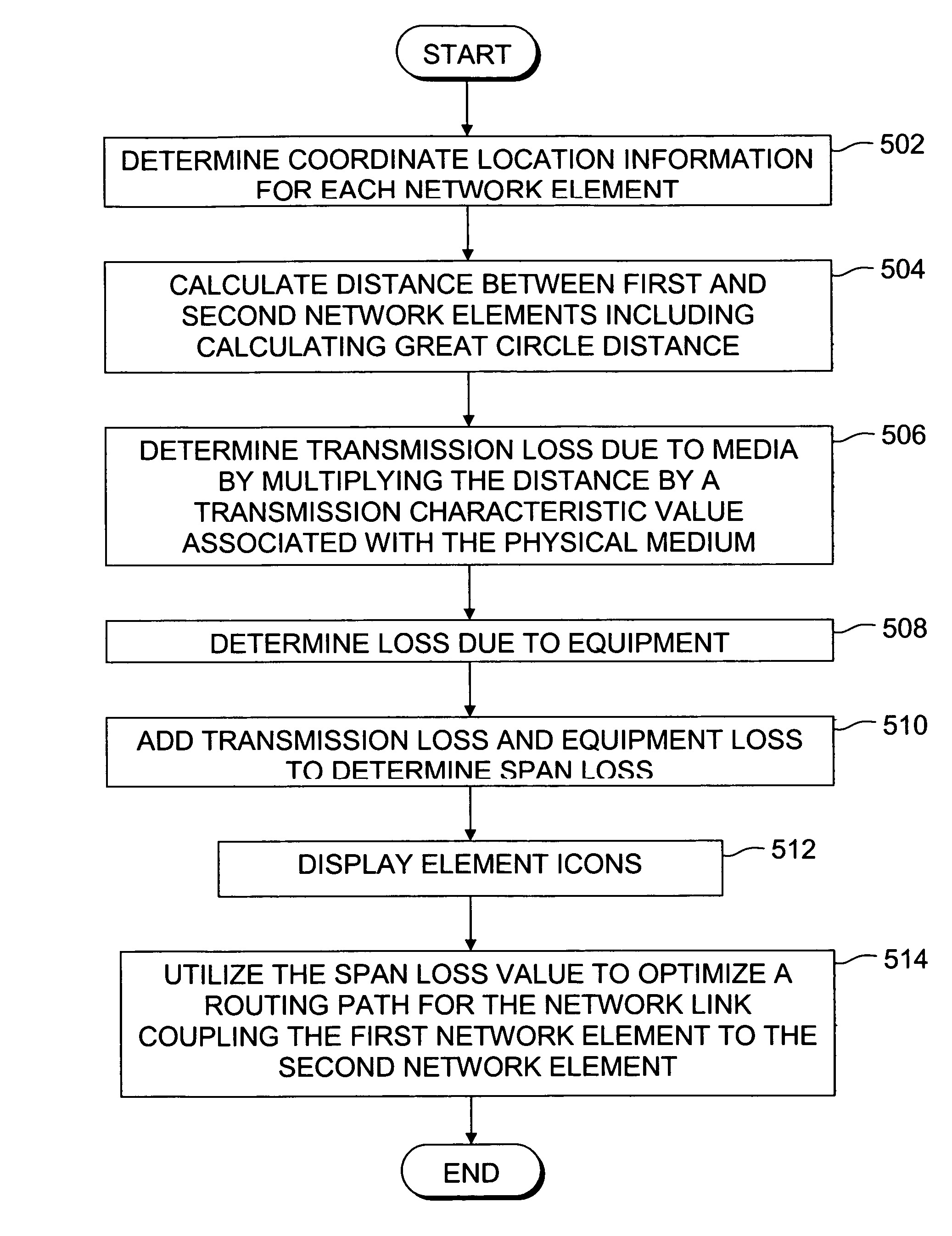
The size of the network can have a great impact on network performance due to signal degradation associated with the transmission media, as well signal degradation due to the network equipment.
However, typical network management systems do not provide an accurate placement of the displayed network element icons in relation to their actual physical location relative to one another, or relative to an absolute coordinate system.
Although some present network management

Method used


Image

  • System and method for locating optical network elements and calculating span loss based on geographic coordinate information
  • System and method for locating optical network elements and calculating span loss based on geographic coordinate information
  • System and method for locating optical network elements and calculating span loss based on geographic coordinate information

Examples


Embodiment Construction

[0016]A system for determining network performance parameters based on geographic location information of network nodes is described. In the following description, for purposes of explanation, numerous specific details are set forth in order to provide a thorough understanding of the present invention. It will be evident, however, to one of ordinary skill in the art, that the present invention may be practiced without these specific details. In other instances, well-known structures and devices are shown in block diagram form to facilitate explanation. The description of preferred embodiments is not intended to limit the scope of the claims appended hereto.

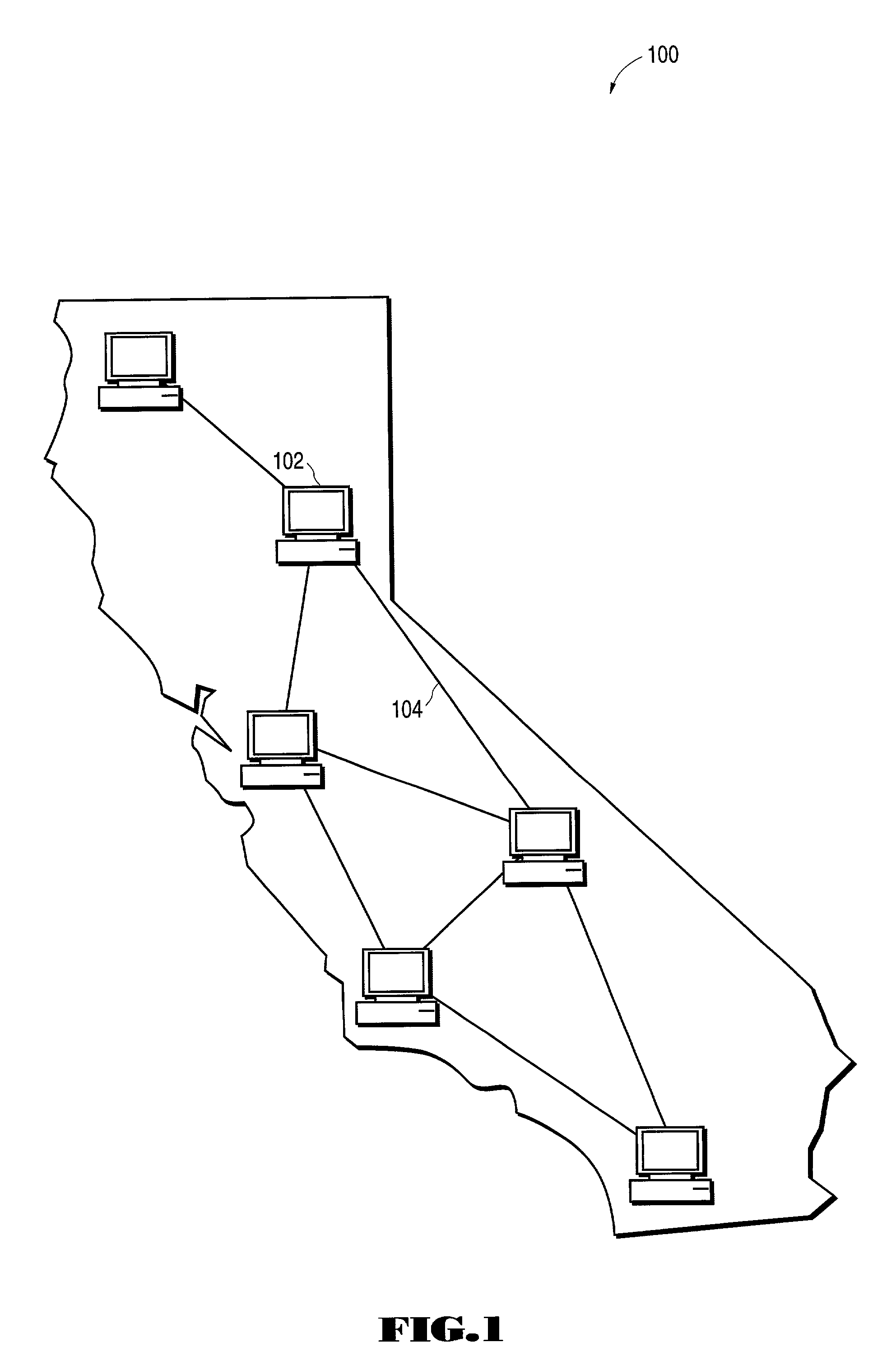
[0017]FIG. 1 illustrates the display screen for a network management system program that implements embodiments of the present invention. As shown in the display screen of FIG. 1, the network elements and links for a long-haul network stretched across California is displayed against a background map of California. Network 100 cons...


PUM


Abstract

A system for locating optical network elements and determining span loss in a network is described. The geographical locations of the first and second network elements in the network are determined with respect to an earth-based coordinate system. A network management system program displays iconic representations of the first and second network elements relative to one another with respect to the coordinate system. The distance between the first and second network elements over a network span linking the two network elements is determined. The transmission loss of the span is determined by multiplying the calculated distance by a transmission loss factor associated with the transmission medium coupling the first and second network elements. The component losses associated with each of the first and second network elements is determined using known specifications or direct measurement. The span loss is determined by adding the component losses with the transmission loss of the medium.

Description

FIELD OF THE INVENTION[0001]The present invention relates generally to data transmission networks, and more specifically to using geographic location information of optical network elements to determine transmission loss characteristics.BACKGROUND OF THE INVENTION[0002]Large-scale optical data transmission networks, such as Wide Area Networks (WANs), often consist of a multitude of different network elements or nodes stretched over vast amounts of area. The distance between network elements is often on the scale of tens or hundreds of miles. In the case of very large-scale networks, often referred to as Metropolitan Area Networks (MANs) or “long-haul networks”, that spread across entire states or countries, the span distances can be very significant. The size of the network can have a great impact on network performance due to signal degradation associated with the transmission media, as well signal degradation due to the network equipment. For such networks, dedicated network eleme...

Claims


Application Information

Patent Timeline
IPC IPC(8): H04L12/26H04L12/24
CPCH04L41/12
Inventor WANG, JIAN L.
Owner FUJITSU LTD
Why Eureka
Try Eureka