Coupling a light sensor array with an optical component

a light sensor array and optical component technology, applied in the field of system-wide light sensor coupled with optical components, can solve the problems of light entering a particular port and traveling to an unassociated light sensor, affecting the performance of the system,

Inactive Publication Date: 2007-12-11
KOTURA
View PDF49 Cites 23 Cited by
  • Summary
  • Abstract
  • Description
  • Claims
  • Application Information

AI Technical Summary

Problems solved by technology

As a result, light from a particular port can enter this region and travel to an unassociated light sensor.
Because cross talk adversely affects the performance of the system, there is a need for a system having reduced cross talk.

Method used


Image

  • Coupling a light sensor array with an optical component
  • Coupling a light sensor array with an optical component
  • Coupling a light sensor array with an optical component

Examples


Embodiment Construction

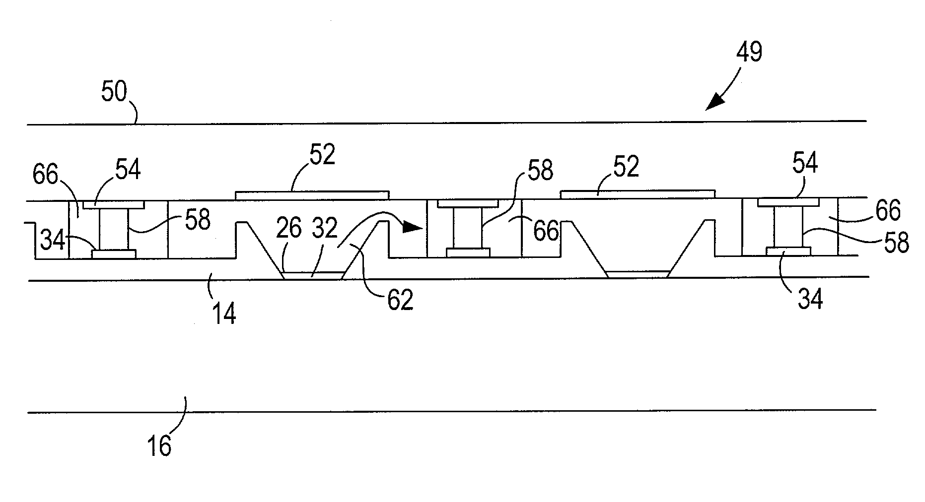
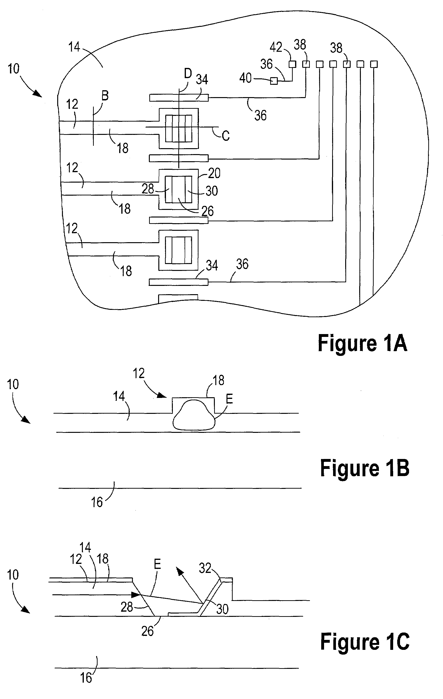
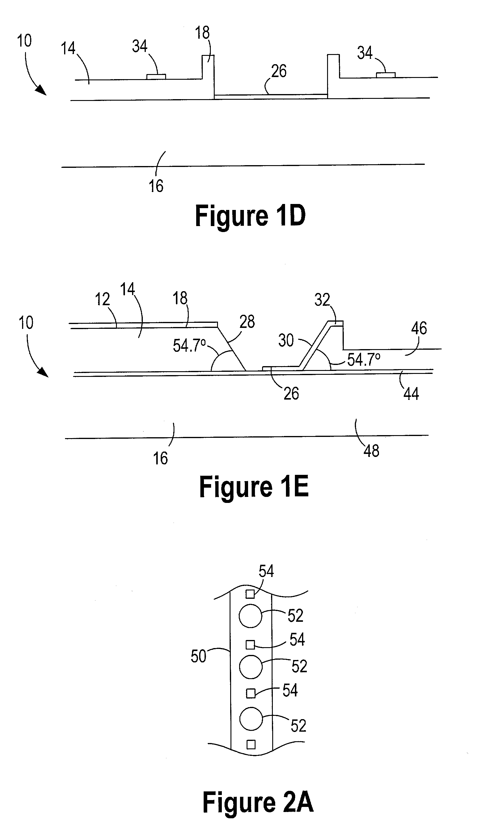
[0030]The invention relates to an optical component system. The system includes an optical component having a plurality of ports through which light signals exit the optical component. The system also includes a light sensor array having a plurality of light sensors. The light sensor array is coupled to the optical component such that different light sensors receive light signals from different ports. As a result, each port is associated with a particular light sensor. The system also includes light barriers between the optical component and the light sensor array. The light barriers are positioned between adjacent light sensors. As a result, the light barriers can prevent a light signal exiting a particular port from traveling to an unassociated light sensor.

[0031]In some instances, the light barrier is positioned between an electrical contact pad on the optical component and an electrical contact pad on the light sensor array. The light barrier can be constructed of an electricall...


PUM


Abstract

An optical component system includes an optical component having a plurality of ports through which light signals exit the optical component. The system also includes a light sensor array having a plurality of light sensors. The light sensor array is coupled to the optical component such that different light sensors receive light signals that exit the optical component through different ports. The system also includes a light barrier positioned between the optical component and the light sensor array and between adjacent light sensors. In some instances, the light barrier is one of a plurality of light barriers that are each positioned between adjacent light sensors.

Description

RELATED APPLICATIONS[0001]This application is related to U.S. patent application Ser. No. 10 / 161,208, filed on May 31, 2002, entitled “Waveguide Tap Monitor” and incorporated herein in its entirety.BACKGROUND[0002]1. Field of the Invention[0003]The invention relates to systems having light sensors coupled with an optical component. In particular, the invention relates to coupling a light sensor array to an optical component.[0004]2. Background of the Invention[0005]A variety of optical component systems include an optical component coupled with one or more light sensors. The optical components include one or more waveguides where light signals are constrained. These waveguides often terminate at a port through which light signals exit the optical component. The light sensor array is often coupled with the optical component so each light sensor receives light from one or more ports. As a result, each light sensor is generally associated with one or more ports on the optical component...

Claims


Application Information

Patent Timeline
Patent Type & Authority Patents(United States)
IPC IPC(8): G02B6/12
CPCG02B6/122G02B6/4249G02B6/4214
Inventor PENG, YIHLIHPINYAN, JAMES A.
Owner KOTURA
Why Eureka
Try Eureka